Lesson 1: OLED Displays
Table of Contents
- Materials
- OLED displays
- The Adafruit GFX Library
- Let’s make stuff!
- Exercises
- Lesson Summary
- Resources
- Next Lesson
Video. Playing Pong on the Adafruit monochrome 1.3” 128x64 pixel OLED display with the Parallax 2-axis joystick and tactile buttons. The source code for Pong is here. Parts of this video are sped up 4x.
In this lesson, you will learn about organic light-emitting diode (OLED) displays, basic graphics programming, and a brief introduction to two serial communication protocols called I2C (Inter-Integrated Circuit) and SPI (Serial Peripheral Interface).
In this lesson, you will learn:
- What OLED displays are and how they differ from LCDs
- The difference between I2C and SPI serial communication protocols and why our OLED display supports both
- How to wire the Adafruit OLED display to your Arduino with I2C
- How to use the Adafruit GFX library to draw shapes, text, and bitmaps
- How the offscreen buffer and
display()rendering pipeline works- How to create animations (bouncing ball) and interactive graphics (sensor-driven visualizations)
- How to build a real-time analog sensor graph on the OLED
Materials
You will need the following materials for this lesson:
| Arduino | OLED Display | Breadboard | Potentiometer |
|---|---|---|---|
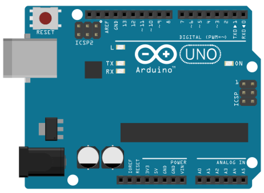 | 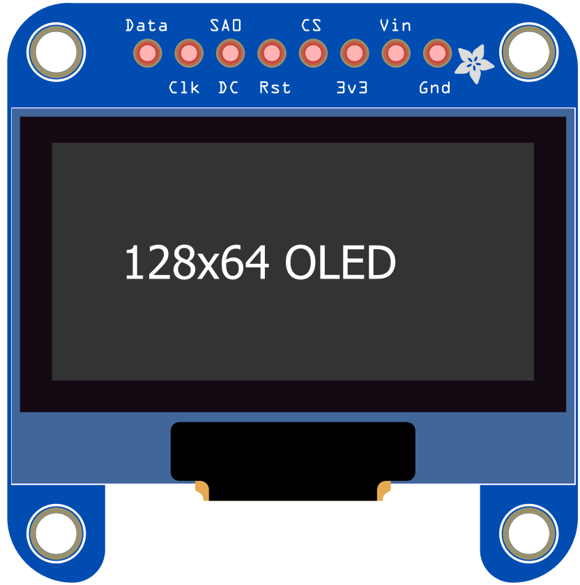 | 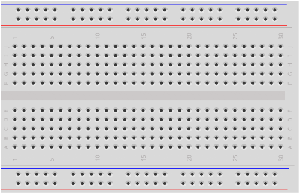 | 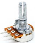 |
| Arduino Uno, Leonardo, or similar | Adafruit 128x64 OLED | Breadboard | 10KΩ Potentiometer (for building interactive demos) |
You will also need jumper wires. If your OLED breakout board has STEMMA QT connectors, you can optionally use a STEMMA QT cable instead of individual jumper wires.
OLED displays
Organic light-emitting diode (OLED) displays are a popular display technology, increasingly used in TVs, computer monitors, smartphones, and handheld game consoles. Unlike LCDs, which require backlighting, each OLED pixel generates its own light, providing superior contrast and color control. This also means that “black” pixels are truly off—consuming no power and producing perfect blacks.
In this lesson, we will be using the monochrome (black-and-white) OLED displays from Adafruit along with their display control and graphics libraries.
I2C and SPI communication protocols
Our OLED display communicates with the Arduino using a serial communication protocol—a standardized method for sending data between electronic devices. The Adafruit SSD1306 breakout board supports two such protocols: I2C (Inter-Integrated Circuit) and SPI (Serial Peripheral Interface). Both are widely used to connect microcontrollers to sensors, displays, and other peripherals, but they make different tradeoffs.
| I2C | SPI | |
|---|---|---|
| Wires needed | 2 data wires (SDA + SCL) plus power/ground | 4+ data wires (MOSI, MISO, SCLK, CS) plus power/ground |
| Speed | Typically 100–400 kHz (standard/fast mode) | Typically 1–10+ MHz |
| Multiple devices | Yes—each device has a unique address on the shared bus (up to 112 devices with 7-bit addressing) | Yes—each device needs its own chip select (CS) line, which uses an additional pin per device |
| Complexity | Simpler wiring; requires pull-up resistors on SDA and SCL (these pull-up resistors are often built into breakout boards like they are with the Adafruit OLED so no external pull-ups are needed for this lesson) | More wires but simpler electrically; no pull-ups needed |
| Best for | Lower-speed peripherals where minimal wiring is important (e.g., sensors, small displays) | Higher-speed peripherals where data throughput matters (e.g., SD cards, large displays) |
For our OLED display, I2C is the default and is what we will use in this lesson. It requires only two data wires (SDA for data and SCL for clock), making the wiring simple. SPI is faster—which can matter for higher frame rates or larger displays—but requires more wires and more GPIO pins. For a small 128x64 monochrome display, I2C is sufficient.
Terminology note: The I2C specification historically used the terms “master” and “slave” to describe the controller device and peripheral devices on the bus. The industry has been moving toward more inclusive terminology: controller and peripheral (or target). We use the newer terms in this lesson. You may still encounter the older terms in datasheets and libraries.
If you’d like to learn more, SparkFun has excellent tutorials on both I2C and SPI.
Install Arduino libraries
To use the Adafruit OLED display, we need two libraries:
- The Adafruit_SSD1306 display driver library, which handles display communication, memory mapping, and low-level drawing routines.
- The Adafruit_GFX graphics library, which provides core graphics routines for all Adafruit displays like drawing points, lines, and circles.
Fortunately, the Arduino IDE makes library installation easy. We can do it right from the IDE itself. Follow our step-by-step installation guide here.
Wiring the Adafruit OLED display
Once you’ve installed the requisite libraries, you’re ready to wire up the display!
As discussed above, the SSD1306 breakout board supports both I2C and SPI communication. We’ll use I2C for this lesson since it requires fewer wires. If you’d like to use SPI mode instead, see Adafruit’s official docs.
While the OLED display requires a 3.3V power supply and 3.3V logic levels for communication, the Adafruit breakout board includes a 3.3V regulator and level shifting on all pins, so you can interface with either 3V or 5V devices. Additionally, recall that I2C requires pull-up resistors on the clock (SCL) and data (SDA) lines so that both are pulled up to logic level HIGH by default. Thankfully, the Adafruit breakout board also includes these resistors. So, the wiring is quite straightforward, consisting of only four wires!
The wiring diagram and circuit schematic are below. We used the Qwiic color-coding system for our wires: blue for data (SDA), yellow for clock (SCL), black for ground (GND), and red for the voltage supply (5V). The I2C pins differ depending on your board. For example, on the Arduino Uno, they are A4 (SDA) and A5 (SCL) rather than digital pins 2 (SDA) and 3 (SCL) as they are on the Leonardo.
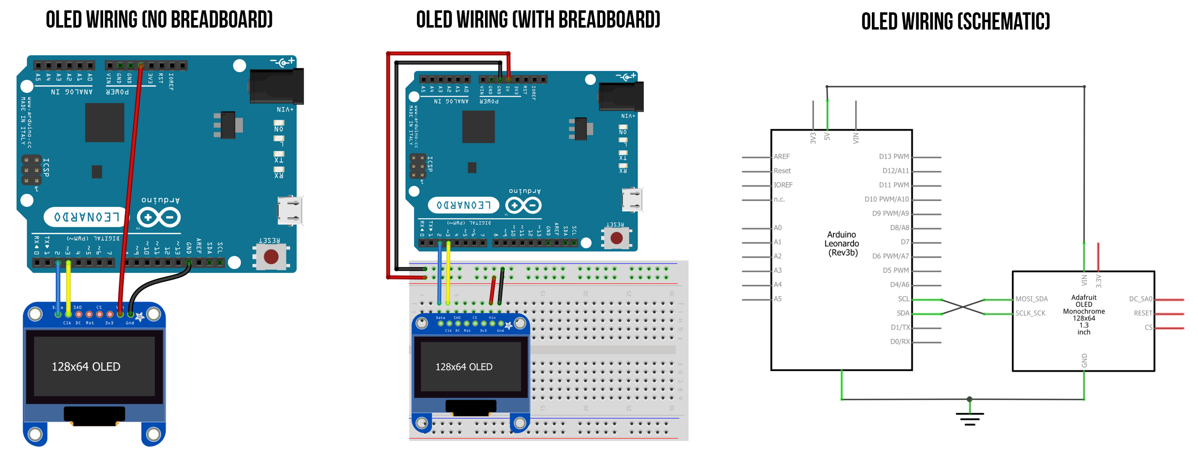 Figure. Wiring the Adafruit OLED display requires only four wires (and nothing else). We used the standard STEMMA QT color coding for our wires: blue for data (SDA), yellow for clock (SCL), black for ground (GND), and red for the voltage supply (5V). Note that the I2C pins differ depending on your board. For example, on the Arduino Uno, they are A4 (SDA) and A5 (SCL) rather than digital pins 2 (SDA) and 3 (SCL) as they are on the Leonardo.
I2C address mismatch: The Adafruit 128x64 OLED uses I2C address
0x3Dby default, but many third-party OLED modules default to0x3C. If your display doesn’t work, try changing the address in your code. You can also run an I2C scanner sketch to detect the address of connected devices.
Physical wiring with jumper cables
Here’s a picture of the OLED wired up using jumper cables.
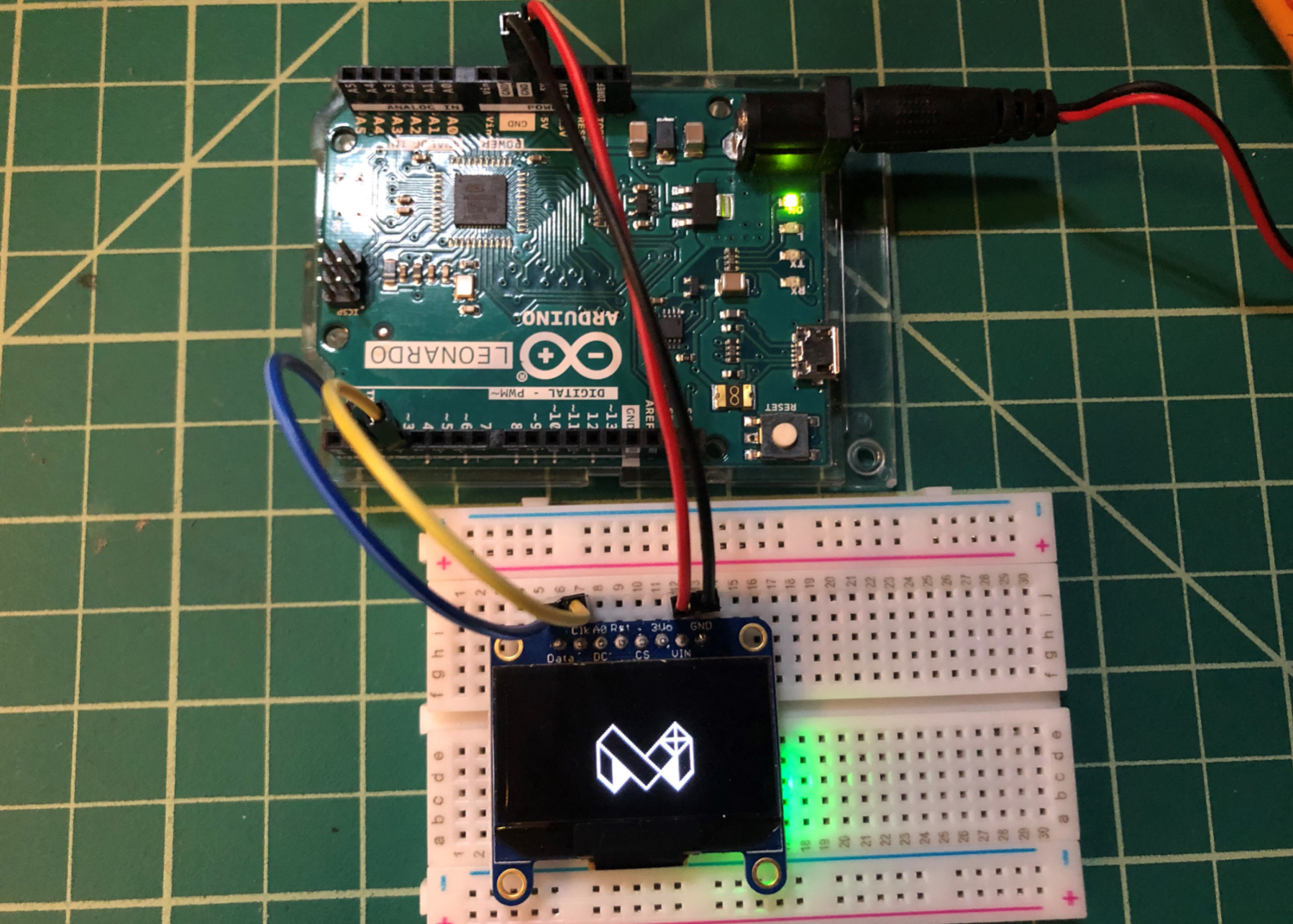 Figure. Physically wiring the OLED display with jumper cables. The Arduino is running this demo code BitmapBounce.ino.
ESP32 wiring
Some students have asked for the ESP32 wiring, so here it is. The ESP32 board runs at 3.3V vs. the 5V supplied by the Arduino Leonardo and Uno; however, the OLED itself only needs 3V for operation. You can learn more about the ESP32 here.
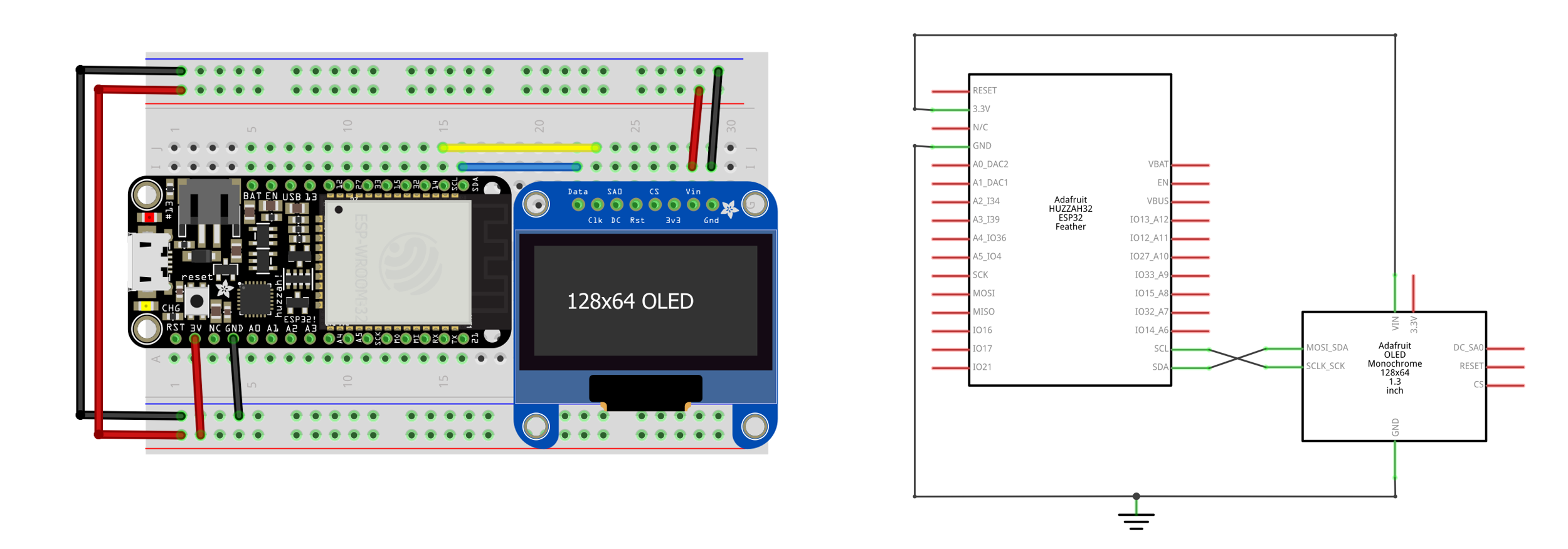 Figure. Wiring diagram for the Adafruit Huzzah32 ESP32 board with OLED.
STEMMA QT wiring
Starting in ~2017, many Adafruit and SparkFun breakout boards began including standardized connectors to more easily connect multiple electronic devices without soldering or working with lots of individual wires. This is particularly helpful because I2C lets us daisy chain I2C-compatible devices together. The SparkFun connection standard for I2C devices, called Qwiic, was later adopted by Adafruit, which they call STEMMA QT.
Both SparkFun and Adafruit sell a variety of Qwiic/STEMMA QT cables, including this female-to-female version (for ~$0.95) and this female-to-male jumper cable version ($0.95). You can use the female-to-female cable to daisy chain multiple devices together.
| STEMMA QT / Qwiic Female-to-Female Cable | STEMMA QT / Qwiic Female-to-Male Jumper Cable |
|---|---|
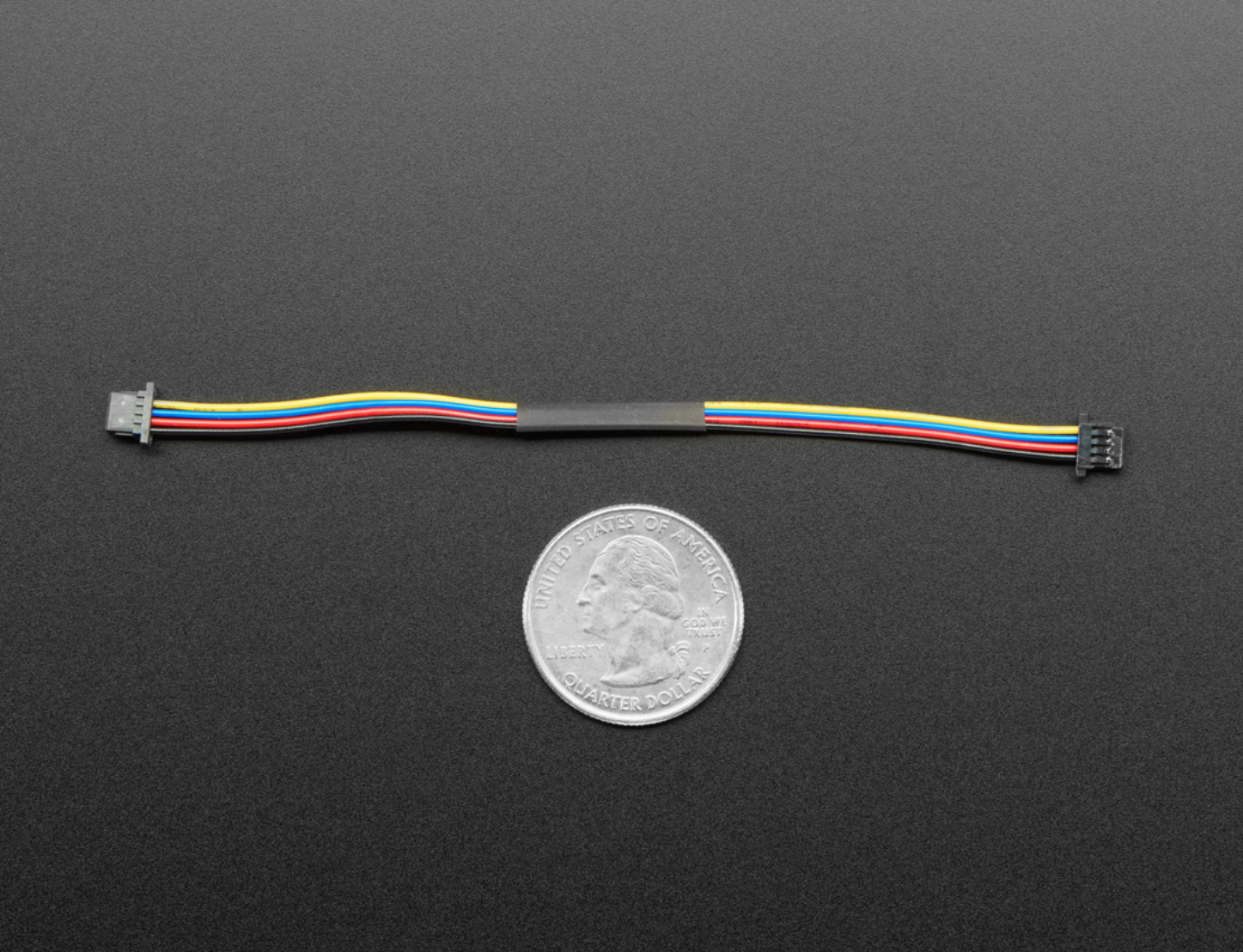 | 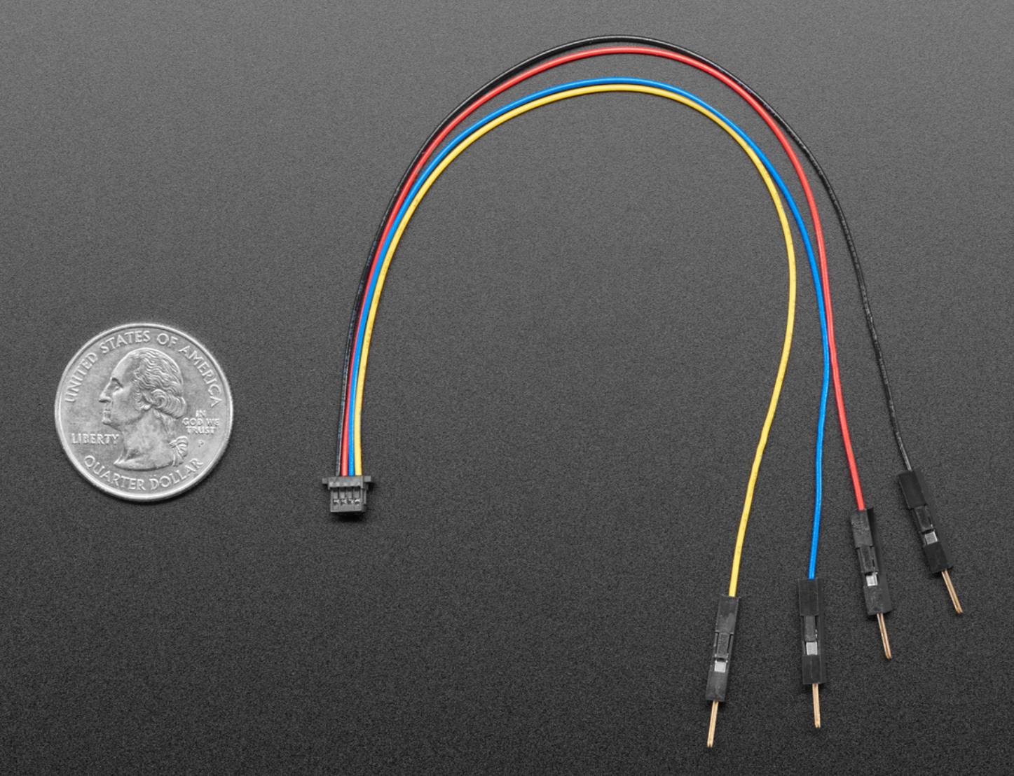 |
The video below shows the OLED display hooked up to a STEMMA QT female-to-male jumper cable:
Video. Running the demo ssd1306_128x64_i2c with a STEMMA QT cable.
Testing the OLED display
Once you’ve wired the OLED display, we’re ready to test it with some code!
We will run one of the examples that ships with the Adafruit_SSD1306 library called ssd1306_128x64_i2c. This example iterates through a variety of drawing demonstrations, including drawing lines, outlining and filling rectangles, circles, rounded rectangles, and triangles, rendering text with different styles, and drawing and animating bitmaps. You can view the example source code here.
To open and run the example, follow these steps.
Step 1: Open the example
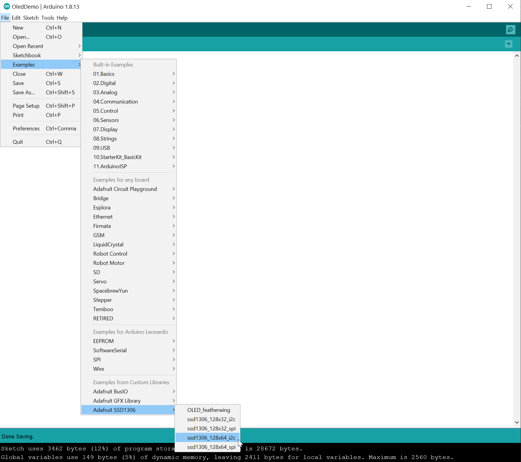
In the Arduino IDE, go to File -> Examples -> Adafruit SSD1306 and select ssd1306_128x64_i2c. You might have to scroll down in the Examples file menu to see it.
Step 2: Compile and upload the example
Now, compile and upload the example.
Step 3: Watch the demo
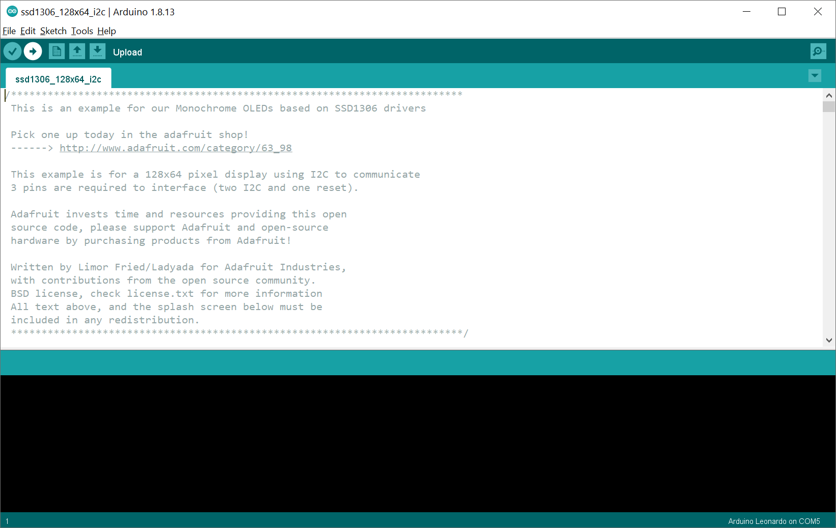
Once the code has compiled and uploaded, it should look something like this:
Video. Running the demo ssd1306_128x64_i2c. Parts of this video are sped up 4x.
If you’re curious how they rendered something, please do look over the source code. There is nothing magic here—reading the code may help inform your future prototypes!
The Adafruit GFX Library
Now that we’ve got our OLED display wired up correctly and tested that it’s working, let’s talk about how to draw to the screen.
To provide a common API for drawing across all Adafruit LCD and OLED displays, Adafruit created a general-purpose graphics rendering library called Adafruit GFX. Put simply, rather than having to individually turn on/off OLEDs in the OLED matrix—which would be tedious (though perhaps a useful learning exercise)—the Adafruit GFX library provides higher-level drawing routines to do this for you, like drawing rectangles, circles, text, and bitmaps.
Though we highly recommend them, you certainly do not have to use the Adafruit SSD1306 and GFX libraries to use OLED displays. There are many tutorials online that describe how to directly interface with the SSD1306 OLED driver and create drawing routines. For example, this “Getting Started With OLED Displays” by JayconSystems on Instructables. Remember, the Adafruit engineers simply built their libraries to make it easier to program OLEDs… and we’re thankful! But you could also follow the SSD1306 and I2C specs and build your own libraries!
Coordinate system and pixels
If you’re familiar with graphics APIs in other programming frameworks—like C#’s System.Drawing library, Processing’s Java drawing library, p5js’ JavaScript drawing library, etc.—the Adafruit GFX library works much the same (at a high level).
The black-and-white OLED consists of a matrix of OLEDs, called pixels, which can be individually addressed to turn on/off (or, in the case of colored displays, to control individual RGB OLEDs to create colors). As with all other drawing libraries, the coordinate system for these pixels places the origin (0,0) at the top-left corner with the x-axis increasing to the right and the y-axis increasing down.
![]() Figure. An overview of the 128x64 matrix of LEDs—we call each LED a “pixel”. We’ve found that students sometimes flip the y-axis in their minds. So, make sure to note how the origin starts at
Figure. An overview of the 128x64 matrix of LEDs—we call each LED a “pixel”. We’ve found that students sometimes flip the y-axis in their minds. So, make sure to note how the origin starts at (0,0) and the x-axis increases to the right and the y-axis increases down. Image created in PowerPoint and uses images from Fritzing and the Adafruit GFX tutorial.
Thus, to turn “on” the LED at pixel (18, 6) using Adafruit GFX, we would write: drawPixel(18, 6, SSD1306_WHITE). For black-and-white displays, the last argument can be either SSD1306_WHITE to draw a white pixel or SSD1306_BLACK to draw a black pixel (these parameters are defined in Adafruit_SSD1306.h). For color displays, you can instead pass in an unsigned 16-bit value representing RGB colors (see docs).
Drawing subsystem
Below, we describe how to draw shapes, text, and bitmaps. Importantly, when you call any of the drawing routines—from drawLine to drawTriangle—you are not drawing directly to the OLED display. Instead, you are drawing to an offscreen buffer handled by the SSD1306 driver. So, after you call your drawing routines, you must then call the void Adafruit_SSD1306::display() function to push the data from RAM to the display. We’ll show how to do this step-by-step in our examples below.
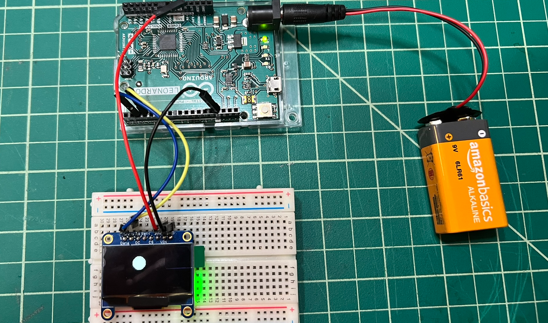 Figure. Let’s begin by drawing a simple circle at
 x,y location of 50,20 with a radius of 10. This code is also on GitHub as DrawCircle.ino; however, that code is slightly different in that it centers the circle in the middle of the screen.
Let’s begin by drawing a circle at x,y location of 50,20 with a radius of 10. We’ll start first with pseudocode to understand the drawing pipeline, then show actual C++.
// One-time initialization
Adafruit_SSD1306 _disp(SCREEN_WIDTH, SCREEN_HEIGHT, &Wire, OLED_RESET);
_disp.begin(SSD1306_SWITCHCAPVCC, 0x3D); // Allocate RAM for image buffer, set VCC, and I2C address

// Drawing
_disp.clearDisplay();                        // Set all pixels to off
_disp.fillCircle(50, 20, 10, SSD1306_WHITE); // Draw to offscreen buffer
_disp.display();                             // Render offscreen buffer to display
And here’s the actual C++ implementation (the full code is on GitHub as DrawCircle.ino).
// Instantiate SSD1306 driver display object
Adafruit_SSD1306 _display(SCREEN_WIDTH, SCREEN_HEIGHT, &Wire, OLED_RESET);

void setup(){
  Serial.begin(9600);

  // Initialize the display using begin()
  // The first parameter is the VCC selection. Typically, pass SSD1306_SWITCHCAPVCC.
  // The second is the address of the display for I2C. Even if you have the display configured
  // for SPI (which doesn't use addresses), you still need to pass a param here (can be 0)
  if (!_display.begin(SSD1306_SWITCHCAPVCC, 0x3D)) { // Address 0x3D for 128x64
    Serial.println(F("SSD1306 allocation failed"));
    for (;;); // Don't proceed, loop forever
  }
}

void loop(){
  // Clear the display
  _display.clearDisplay();

  // Put in drawing routines
  // In this case, draw a circle at x,y location of 50,20 with a radius of 10
  _display.fillCircle(50, 20, 10, SSD1306_WHITE);

  // Render graphics buffer to screen
  _display.display();
}
Now, because we are drawing the exact same thing on every loop() call, we could just as well put this drawing code into setup() and have it draw once and only once (the graphic content will persist).
// Instantiate SSD1306 driver display object
Adafruit_SSD1306 _display(SCREEN_WIDTH, SCREEN_HEIGHT, &Wire, OLED_RESET);

void setup(){
  Serial.begin(9600);

  // Initialize the display. If it fails, print failure to Serial
  // and enter an infinite loop
  if (!_display.begin(SSD1306_SWITCHCAPVCC, 0x3D)) { // Address 0x3D for 128x64
    Serial.println(F("SSD1306 allocation failed"));
    for (;;); // Don't proceed, loop forever
  }

  // Clear the display
  _display.clearDisplay();

  // Draw a circle at x,y location of 50,20 with a radius of 10
  _display.fillCircle(50, 20, 10, SSD1306_WHITE);

  // Render graphics buffer to screen
  _display.display();
}

void loop(){
  // Empty on purpose to make a point about how graphic content persists
  // on screen
}
However, for practical purposes, we always want to put our drawing methods in loop() because we want to support dynamic graphics, which are animated (e.g., graphics that change over time) and/or responsive (e.g., graphics that change in response to input).
Don’t forget
_display.display()!You need to call
_display.display()to render the graphics buffer to the screen. It’s not sufficient to simply calldrawCircle,fillRect, ordrawBitmap—those functions only “draw” to an offscreen buffer. If you look at the Adafruit_SSD1306.cpp source on GitHub, you’ll see thatvoid Adafruit_SSD1306::display(void)“pushes data currently in RAM to the SSD1306 display.” This is a very common mistake!
Drawing shapes
The Adafruit GFX library currently supports drawing lines, rectangles, circles, rounded rectangles, and triangles. For all shapes, you can draw an outlined version (e.g., drawRect) or a filled version (e.g., fillRect). The images below are from the Adafruit GFX tutorial.
| Shape and API call | Output |
|---|---|
Linesvoid drawLine(uint16_t x0, uint16_t y0, uint16_t x1, uint16_t y1, uint16_t color); |  drawLine(5, 10, 3, 19, SSD1306_WHITE) |
Rectanglesvoid drawRect(uint16_t x0, uint16_t y0, uint16_t w, uint16_t h, uint16_t color); void fillRect(uint16_t x0, uint16_t y0, uint16_t w, uint16_t h, uint16_t color); |  drawRect(3, 2, 13, 10, SSD1306_WHITE) |
Circlesvoid drawCircle(uint16_t x0, uint16_t y0, uint16_t r, uint16_t color); void fillCircle(uint16_t x0, uint16_t y0, uint16_t r, uint16_t color); |  drawCircle(14, 8, 7, SSD1306_WHITE) |
Ellipsesvoid drawEllipse(int16_t x0, int16_t y0, int16_t rw, int16_t rh, uint16_t color); void fillEllipse(int16_t x0, int16_t y0, int16_t rw, int16_t rh, uint16_t color); | drawEllipse(14, 8, 10, 5, SSD1306_WHITE) |
Rounded Rectanglesvoid drawRoundRect(uint16_t x0, uint16_t y0, uint16_t w, uint16_t h, uint16_t radius, uint16_t color); void fillRoundRect(uint16_t x0, uint16_t y0, uint16_t w, uint16_t h, uint16_t radius, uint16_t color); |  drawRoundRect(3, 1, 17, 12, 5, SSD1306_WHITE) |
Rotated Rectanglesvoid drawRotatedRect(int16_t cenX, int16_t cenY, int16_t w, int16_t h, int16_t angleDeg, uint16_t color); void fillRotatedRect(int16_t cenX, int16_t cenY, int16_t w, int16_t h, int16_t angleDeg, uint16_t color); | drawRotatedRect(32, 16, 20, 10, 45, SSD1306_WHITE) |
Trianglesvoid drawTriangle(uint16_t x0, uint16_t y0, uint16_t x1, uint16_t y1, uint16_t x2, uint16_t y2, uint16_t color); void fillTriangle(uint16_t x0, uint16_t y0, uint16_t x1, uint16_t y1, uint16_t x2, uint16_t y2, uint16_t color); |  drawTriangle(6, 13, 9, 2, 18, 9, SSD1306_WHITE) |
Drawing custom shapes
You can, of course, create custom shapes either by cleverly combining shape primitives (e.g., a rectangle and a triangle to make a basic house) or by implementing your own drawing algorithm and calling drawPixel. The drawPixel API looks like:
| Shape and API call | Output |
|---|---|
Pixelsvoid drawPixel(uint16_t x, uint16_t y, uint16_t color); |  drawPixel(0, 0, SSD1306_WHITE) drawPixel(18, 6, SSD1306_WHITE) drawPixel(6, 13, SSD1306_WHITE) |
Optimized vertical and horizontal line drawing
If you are drawing purely vertical or horizontal lines, you can use optimized line-drawing functions that avoid angular calculations. For example, we use drawFastVLine in our analog graphing demos below.
For more information and examples, see the Basic Drawing section of Last Minute Engineers’ OLED display tutorial.
Drawing text
There are two methods to render text: drawing a single character with drawChar and using the print rendering subsystem, which mimics the familiar Serial.print() functionality covered in our Intro to Arduino series here.
Method 1: drawChar
To draw a single character, you specify an (x, y) location, the character, the foreground and background color, and a size. By default, characters are 5x8 pixels but an optional size parameter (the last argument) can be passed to scale the font (e.g., a size of 2 will render 10x16 pixels per character).
| Text API call | Output |
|---|---|
Charvoid drawChar(uint16_t x, uint16_t y, char c, uint16_t color, uint16_t bg, uint8_t size); |  drawChar(3, 4, 'A', SSD1306_WHITE, SSD1306_BLACK, 1) |
Method 2: Print rendering
The more common and feature-rich method to draw text is via the print subsystem. Interestingly, the Adafruit_GFX class actually extends the Print class from the Arduino core library. You can view the Serial.print() docs here; the API is the same for the OLED.
Rather than call Serial.print("Hello World"), however, with the OLED display and Adafruit GFX library, you would call _display.print("Hello World"). Here, _display is the Adafruit_SSD1306 object.
To use the OLED’s print functionality, you can first set optional parameters such as the text color, size, and wrapping:
void setTextColor(uint16_t color);
void setTextColor(uint16_t color, uint16_t backgroundcolor);
void setTextSize(uint8_t size);
void setTextWrap(boolean w);
Then, to position the text, you set the print cursor with:
void setCursor(uint16_t x0, uint16_t y0);
Finally, to print the text at that cursor position, you can call any of the standard Serial.print methods, including this subset:
size_t print(const String &);
size_t print(const char[]);
size_t print(char);

size_t println(const String &s);
size_t println(const char[]);
size_t println(char);
See the Serial.print() docs or the Print.h library for more on the print API, or read on for an example.
Centering text
In creative coding, visualization, and game dev, we often want to center or otherwise align text. To do so, we need to measure it. Fortunately, the Adafruit GFX library has a method called getTextBounds that does just that!
/**************************************************************************/
/*!
    @brief  Helper to determine size of a string with current font/size.
            Pass string and a cursor position, returns upper-left corner and width and height
    @param  str  The ASCII string to measure
    @param  x    The current cursor X
    @param  y    The current cursor Y
    @param  x1   The boundary X coordinate, returned by function
    @param  y1   The boundary Y coordinate, returned by function
    @param  w    The boundary width, returned by function
    @param  h    The boundary height, returned by function
*/
/**************************************************************************/
void getTextBounds(String &str, int16_t x, int16_t y, int16_t *x1, int16_t *y1, uint16_t *w, uint16_t *h);
For example, in our HelloWorld.ino example, we center the text “Hello Makers!” both vertically and horizontally on the OLED screen. The key excerpt is here:
int16_t x, y;
uint16_t textWidth, textHeight;
const char strHello[] = "Hello Makers!";

// Setup text rendering parameters
_display.setTextSize(1);
_display.setTextColor(WHITE, BLACK);

// Measure the text with those parameters. Pass x, y, textWidth, and textHeight
// by reference so that they are set within the function itself.
_display.getTextBounds(strHello, 0, 0, &x, &y, &textWidth, &textHeight);

// Center the text on the display (both horizontally and vertically)
_display.setCursor(_display.width() / 2 - textWidth / 2, _display.height() / 2 - textHeight / 2);

// Print out the string
_display.print(strHello);

// Render the graphics buffer to screen
_display.display();
Inverting text
We can also invert the text simply by switching the colors in setTextColor(uint16_t color, uint16_t backgroundcolor). So, to draw black text on a white background, we would write _display.setTextColor(BLACK, WHITE);
| setTextColor(WHITE, BLACK) | setTextColor(BLACK, WHITE) |
|---|---|
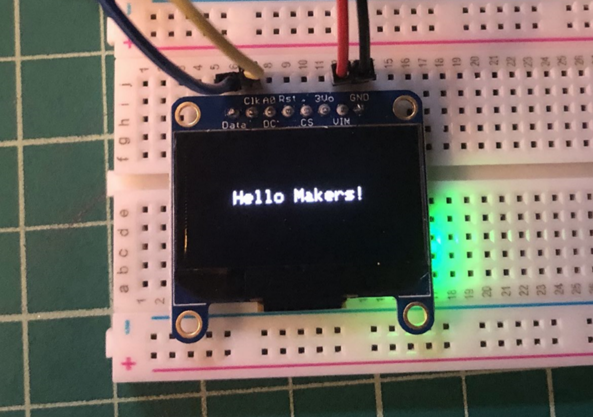 | 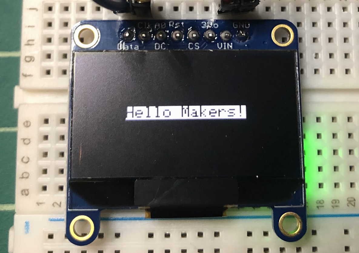 |
Drawing the embedded font graphics
You can draw the embedded font graphics either using drawChar or, similar to Serial.write(), the Adafruit GFX library also supports the write() function.
While you can use either drawChar or write, the latter uses the currently set setText parameters like setTextSize and setTextColor—which is helpful. Below, we’re printing out all of the glyphs embedded in the default font, which includes embedded graphics like smiley faces, hearts, spades, etc.
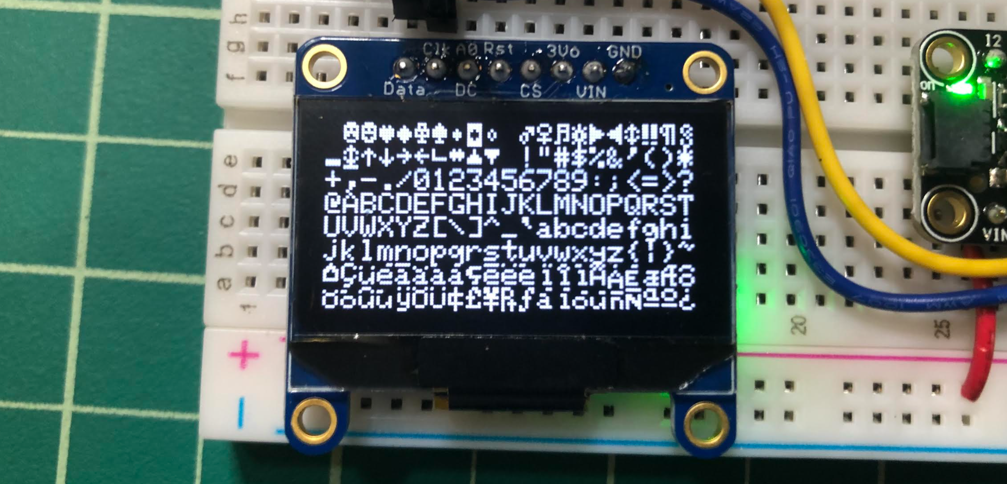 Figure. Drawing the embedded glyphs in the default font using
 _display.write(). This code is called DrawAllChars.ino in our GitHub.
To draw a happy face—which is char index 2—in the middle of the screen, for example, we could use drawChar:
const int CHAR_WIDTH = 5;
const int CHAR_HEIGHT = 8;

int charSize = 3;
int charWidth = charSize * CHAR_WIDTH;
int charHeight = charSize * CHAR_HEIGHT;
int charIndex = 2; // for smiley face

uint16_t yText = _display.height() / 2 - charHeight / 2;
uint16_t xText = _display.width() / 2 - charWidth / 2;

_display.drawChar(xText, yText, (char)charIndex, SSD1306_WHITE, SSD1306_BLACK, charSize);
Or we could also use the write() method:
int16_t x1, y1;
uint16_t textWidth, textHeight;
int charIndex = 2; // for smiley face

_display.setTextSize(3);
_display.getTextBounds("X", 0, 0, &x1, &y1, &textWidth, &textHeight);
uint16_t yText = _display.height() / 2 - textHeight / 2;
uint16_t xText = _display.width() / 2 - textWidth / 2;
_display.setCursor(xText, yText);
_display.write(charIndex);
Here’s an example iterating through all of the glyphs individually, which demonstrates the code above. You can use either drawChar or write—we demonstrate both in DrawChar.ino.
Video. A demonstration of DrawChar.ino showing how to draw the embedded graphics from the default font.
Loading custom fonts
In addition to the default fixed-size, mono-spaced font, you can also load and render an alternative font. See the “Loading Fonts” section of the Adafruit GFX tutorial.
You can also make your own font or custom symbols for your font. See the Adafruit tutorial: “Creating Custom Symbol Fonts for Adafruit GFX Library”.
Drawing bitmaps
Finally, you can load and render custom bitmaps on the display. See “Displaying Bitmaps” on Last Minute Engineers.
Adafruit GFX Resources
Before moving forward, we strongly encourage you to read the official Adafruit GFX tutorial and the “Last Minute Engineers” OLED tutorial—both offer great overviews of the Adafruit GFX library and how to display text, draw shapes, and load and display bitmaps.
In addition, you can:
-
View the Adafruit GFX library source code here, including the Adafruit_GFX.h, which shows the available API. Yes, depending on your familiarity with C++ and reading
.hfiles, this might be intimidating or overwhelming—but it’s important to demystify these libraries. They are just source code that devs wrote. And, with experience, you could too! -
Examine our own OLED examples here, including the Hello World example mentioned above, a simple animation example called BallBounce, an object-oriented version of this animation using the Shape.hpp class from the Makeability Lab Arduino library, and simple games such as a collision test, Pong, and Flappy Bird. We’ll go over some of these below.
Let’s make stuff!
In this part of the lesson, we are going to make a variety of OLED-based creations. This should be fun! As mentioned, we have a GitHub repo of OLED examples, some of which we describe below.
Activity: draw shapes and text
First, to get a feel for the Adafruit GFX API and the coordinate system, let’s simply draw some text and shapes to the screen. You get to choose what you want to draw and where. Think of it like abstract shape art!
Remember, in loop(), you need to:
// Clear the display. If we don't do this, we'll simply be drawing over our
// previous renderings (which you may sometimes want but generally not)
_display.clearDisplay();

// Put in drawing routines
drawStuff();

// Render graphics buffer to screen
_display.display();
We made a version called SimpleDrawingDemo.ino that draws shapes of random sizes and locations on each frame, but you could do something even simpler (or more complex)!
Video. A demonstration of SimpleDrawingDemo.ino.
Shape drawing prototyping journal activity
For your prototyping journals, create your own shape/text drawing demo. Take a picture or, if there is animation, record a short video or animated gif. In your journals, link to the code, insert the pictures/videos, and reflect on what you learned.
Activity: draw a bouncing ball
Now that we’ve gained some familiarity with the drawing API and graphics pipeline, let’s learn a bit about animation.
We are going to draw a simple bouncing ball around the screen. Bouncing or reflecting objects are one of the key components of many games, including Pong, Arkanoid, etc.
To create a bouncing ball, we need to:
- Track the x,y location of the ball across frames.
- Set an x,y speed in pixels per frame—that is, how much does the ball move per frame? For smoother animation, we could track x,y speed in terms of time (e.g., pixels/second); however, this is slightly more complicated (e.g., it requires tracking timestamps in the code, computing time deltas, etc.). For our purposes, tracking x,y speed in terms of pixels/frame is fine.
- Check for collisions when the ball collides with the ceiling, floor, or walls of the screen. When a collision occurs, simply reverse the direction of the ball.
- Draw the circle at the given x,y location.
Prototyping ideas with p5js
Here’s a demo of a bouncing ball we made in p5js. Sometimes, it’s useful to prototype a visualization or game idea in a rapid programming environment like p5js or Processing before coding it up in C++ for Arduino (and it’s easier to debug in those environments as well). You can edit and play with this demo in your browser here using the p5js online editor.
Video. A video of the Ball Bounce demo created in p5js. You can edit the source code and run it live in the p5js online editor here. Alternatively, you can view the source in our p5js GitHub repo.
C++ implementation using Adafruit GFX
For the C++ implementation using the Adafruit GFX library and Arduino, the key bits of code are excerpted below. The overall implementation is quite similar to the p5js version. Make sure you read over this code carefully and understand it.
Again, rather than, say, “miles per hour” or “pixels per second”, we’ve defined speed as “pixels per frame”—that is, how many pixels does the object move per frame. If we set _xSpeed to 5 and _ySpeed to 0, then the ball would move 5 pixels in x per frame (and simply bounce back and forth from the left side of the screen to the right and back again).
// Create the display object
Adafruit_SSD1306 _display(128, 64, &Wire, 4);

// Ball global variables
const int _ballRadius = 5;
int _xBall = 0;  // x location of the ball
int _yBall = 0;  // y location of the ball
int _xSpeed = 0; // x speed of ball (in pixels per frame)
int _ySpeed = 0; // y speed of ball (in pixels per frame)

void setup() {
  // Initialize the display
  _display.begin(SSD1306_SWITCHCAPVCC, 0x3D);

  // Gets a random long between min and max - 1
  // https://www.arduino.cc/reference/en/language/functions/random-numbers/random/
  _xSpeed = random(1, 4);
  _ySpeed = random(1, 4);
}

void loop() {
  // Clear the display
  _display.clearDisplay();

  // Update ball based on speed location
  _xBall += _xSpeed;
  _yBall += _ySpeed;

  // Check for ball bounce. First check for going off left or right side of screen
  if(_xBall - _ballRadius <= 0 || _xBall + _ballRadius >= _display.width()){
    _xSpeed = _xSpeed * -1; // reverse x direction
  }

  // Now check for bouncing on floor or ceiling
  if(_yBall - _ballRadius <= 0 || _yBall + _ballRadius >= _display.height()){
    _ySpeed = _ySpeed * -1; // reverse y direction
  }

  // Draw circle
  _display.drawCircle(_xBall, _yBall, _ballRadius, SSD1306_WHITE);

  // Render buffer to screen
  _display.display();
}
You can view the full code on GitHub as BallBounce.ino.
Bitmap bounce
We also have a similar “bounce” demo, called BitmapBounce.ino, that uses a bitmap rather than a graphic primitive. To create the bitmap byte dump, we used this image2cpp tool on this Makeability Lab logo.
Video. A video of BitmapBounce.ino.
Animation prototyping journal activity
For your prototyping journals, create a custom animation demo, record a short video or animated gif, link to the code, and reflect on what you learned. As one simple example, change the object bouncing around from a circle to a rectangle. If you want something more challenging, try bouncing a triangle around the screen and using the entry angle and triangle angles to properly calculate the reflection (it’s probably easiest to do this using vector calculations). Or you could use the drawLine method to animate rainfall similar to this Purple Rain video by the Coding Train. While this was made for p5js, it would be fairly straightforward to translate to Arduino and the Adafruit GFX library.
Activity: interactive graphics
Finally, for our last activity, let’s make a few interactive prototypes—that is, graphics that respond to digital or analog input. Interactivity captures the true essence of physical computing. And for an HCI professor like me, this is where the joy really begins!
Demo 1: Setting ball size based on analog input
We’ll start with changing a shape’s size based on sensor input. While you can use whatever sensor you want, for this demonstration, we will use our ole trusty potentiometer hooked up to A0.
The OLED + pot circuit
Here’s the circuit. Same as before but we’ve added a 10K potentiometer.
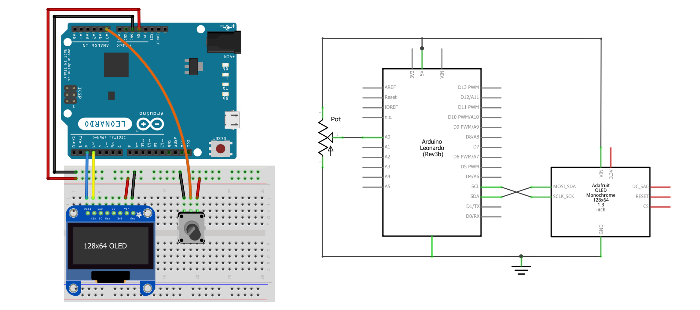 Figure. A basic OLED circuit with potentiometer input on
 A0.
The OLED + pot code
The code is simple: read the analog input and use it to set the circle’s radius.
void loop() {
  // On each loop, we'll want to clear the display so we're not writing over
  // previously drawn data
  _display.clearDisplay();

  // Read the analog input value
  int sensorVal = analogRead(ANALOG_INPUT_PIN);

  // The maximum radius is either the display width or height, whichever is smallest
  int maxRadius = min(_display.width(), _display.height());

  // Now calculate the radius based on the sensor val
  int radius = map(sensorVal, 0, MAX_ANALOG_INPUT, 0, maxRadius);

  // Center the circle
  int xCircle = _display.width() / 2;
  int yCircle = _display.height() / 2;

  // Draw it on the screen
  _display.fillCircle(xCircle, yCircle,  radius, SSD1306_WHITE);

  // Render the graphics buffer to screen
  _display.display();

  delay(50);
}
You can view the full code on GitHub as AnalogBallSize.ino.
Video. A video of AnalogBallSize.ino.
Demo 2: Setting ball location based on analog input
Now let’s hook up two analog inputs to control the x,y location of the circle rather than the size. In this case, we’ll use two potentiometers. The wiring diagram is below.
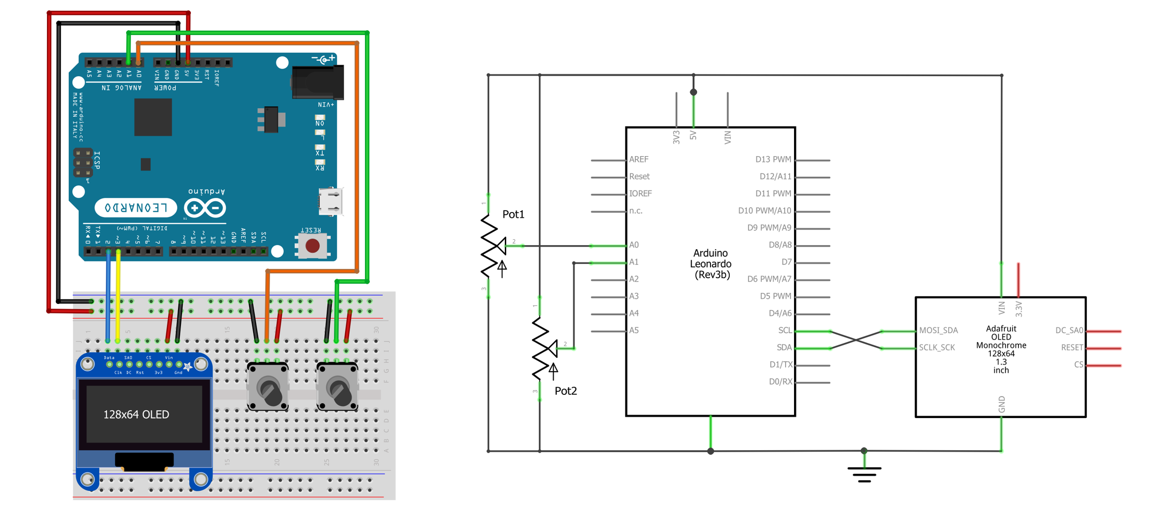 Figure. The wiring and circuit diagram for two potentiometers and the OLED display.
For the code, it’s very similar to AnalogBallSize.ino, but we translate the analogRead values to x and y locations:
void loop() {
  // On each loop, we'll want to clear the display so we're not writing over
  // previously drawn data
  _display.clearDisplay();

  // Read the analog input value
  int xSensorVal = analogRead(X_ANALOG_INPUT_PIN);
  delay(1); // give ADC time
  int ySensorVal = analogRead(Y_ANALOG_INPUT_PIN);

  // Translate sensor readings to x, y pixel locations
  int xLoc = map(xSensorVal, 0, MAX_ANALOG_INPUT, 0, _display.width());
  int yLoc = map(ySensorVal, 0, MAX_ANALOG_INPUT, 0, _display.height());

  // Draw it on the screen
  _display.fillCircle(xLoc, yLoc,  BALL_RADIUS, SSD1306_WHITE);

  // Render the graphics buffer to screen
  _display.display();

  delay(50);
}
You can view the full code on GitHub as AnalogBallLocation.ino.
Video. A demonstration of AnalogBallLocation.ino using potentiometers on A0 and A1.
Demo 3: Basic real-time analog graph
One of the most famous Arduino + Processing demos is the real-time analog sensor graph (link): the Arduino reads sensor data using analogRead, then transmits it to the computer using Serial.println(), where it is parsed and graphed using Processing.
With the OLED display and the Adafruit GFX library, we can easily recreate this entirely on the Arduino!
The idea is simple: read in a sensor value as sensorVal, draw a vertical line at xPos of a length proportional to sensorVal, increment xPos, repeat. When xPos >= _display.width(), set xPos back to zero, clear the display, and start the whole process over.
Notably, this code takes advantage of selectively calling _display.clearDisplay(). Unlike the other examples we’ve shared thus far—which clear the display on each frame—here, we take advantage of graphics persisting across _display.display() calls to “build up” our graph over time. That is, we only draw one new line per new sensor input, which persists on the screen until _xPos >= _display.width(), at which point we call _display.clearDisplay().
void loop() {

  // Read the analog voltage value
  int analogVal = analogRead(ANALOG_INPUT_PIN);

  // Draw the line for the given sensor value
  int lineHeight = map(analogVal, MIN_ANALOG_INPUT, MAX_ANALOG_INPUT, 0, _graphHeight);
  int yPos = _display.height() - lineHeight;

  // For purely horizontal or vertical lines, there are optimized line-drawing
  // functions that avoid costly angular calculations
  _display.drawFastVLine(_xPos++, yPos, lineHeight, SSD1306_WHITE);
  _display.display();

  // If the x-position is off the right side of the screen, clear the display
  // and start the graph over
  if (_xPos >= _display.width()) {
    _xPos = 0;
    _display.clearDisplay();
  }

  delay(10);
}
The full source code is available in our OLED GitHub as AnalogGraph.ino. Here’s a video demo:
Video. A demonstration of AnalogGraph.ino using a potentiometer for analog input on A0. We also show the currently sensed A0 value in the upper-left corner and our frame rate (fps) in the upper-right corner.
Demo 4: Real-time scrolling analog graph
A slightly improved but more complicated version of the analog graph is a scrolling implementation. Rather than clearing the display when xPos >= _display.width(), we simply “scroll” the content to the left. For memory and computational efficiency, we implement this with a circular buffer, which is the size of our screen width (so, 128 values—one for each x pixel).
Look over the code. Does it make sense?
int _circularBuffer[SCREEN_WIDTH]; //fast way to store values
int _curWriteIndex = 0; // tracks where we are in the circular buffer

void loop() {
  // Clear the display on each frame. We draw the entire graph on each frame
  // from the _circularBuffer
  _display.clearDisplay();

  // Read and store the analog data into a circular buffer
  int analogVal = analogRead(ANALOG_INPUT_PIN);
  Serial.println(analogVal);
  _circularBuffer[_curWriteIndex++] = analogVal;

  // Set the circular buffer index back to zero when it reaches the
  // right of the screen
  if(_curWriteIndex >= _display.width()){
    _curWriteIndex = 0;
  }

  // Draw the line graph based on data in _circularBuffer
  int xPos = 0;
  for (int i = _curWriteIndex; i < _display.width(); i++){
    int analogVal = _circularBuffer[i];
    drawLine(xPos, analogVal);
    xPos++;
  }

  for(int i = 0; i < _curWriteIndex; i++){
    int analogVal = _circularBuffer[i];
    drawLine(xPos, analogVal);
    xPos++;
  }

  _display.display();

  delay(10);
}
The full source code is available in our OLED GitHub as AnalogGraphScrolling.ino. Here’s a video demo.
Video. A demonstration of AnalogGraphScrolling.ino using a potentiometer for analog input on A0. We also show the currently sensed A0 value in the upper-left corner and our frame rate (fps) in the upper-right corner.
Which graph version do you prefer? AnalogGraph.ino or AnalogGraphScrolling.ino? We personally prefer the latter!
Interactive graphics prototyping journal activity
For your prototyping journals, rapidly prototype an interactive OLED demo using a sensor of your own choosing and design a simple visualization or responsive graphic around that input. In your journal, include a brief description with a short video (or animated gif) and reflect on what you learned. As one simple idea: how about combining animation + interactivity? What if you changed the ball speed in BallBounce.ino based on sensed input?
Exercises
Want to go further? Here are some challenges to reinforce what you’ve learned:
- Etch-a-Sketch. Use two potentiometers to control an x,y cursor that draws a persistent trail on the OLED—like a tiny Etch A Sketch. Add a button to clear the screen. Can you add line thickness control with a third pot?
- Digital thermometer. If you have a temperature sensor (like the TMP36), read the temperature and display it in large text on the OLED. Bonus: add a scrolling graph of temperature over time!
- Game time. Extend the BallBounce.ino demo into a simple game. Add a paddle controlled by a potentiometer (like Pong) or add obstacles on screen. Check out our Pong and Flappy Bird examples for inspiration!
- Multi-sensor dashboard. Hook up two or more sensors (e.g., a potentiometer and a photoresistor) and display both readings simultaneously on the OLED—perhaps as numeric values, bar graphs, or a split-screen graph.
- Custom bitmap. Use the image2cpp tool to convert a small image into a bitmap array, then display it on the OLED. Try animating it by moving it across the screen (like BitmapBounce.ino).
Lesson Summary
In this lesson, you explored OLED displays and learned how to create graphics, animations, and interactive visualizations on a small screen. The key concepts were:
- OLED displays use organic light-emitting diodes where each pixel generates its own light, unlike LCDs that require backlighting. This provides superior contrast and true blacks.
- The Adafruit OLED breakout board supports two serial communication protocols: I2C (2 data wires, simpler wiring, lower speed) and SPI (4+ data wires, faster throughput). We used I2C in this lesson since it requires fewer wires and is more than fast enough for our small monochrome display. The Adafruit breakout board conveniently includes built-in pull-up resistors and a voltage regulator for I2C.
- The Adafruit SSD1306 library handles display communication and the Adafruit GFX library provides a common drawing API for shapes, text, and bitmaps.
- Drawing uses an offscreen buffer pattern: you call drawing functions (like
drawCircle,fillRect,print) to render into RAM, then call_display.display()to push the buffer to the screen. - The coordinate system places the origin
(0,0)at the top-left corner, with x increasing right and y increasing down. - Animation is achieved by updating positions each frame within
loop(), clearing the display, drawing at the new position, and callingdisplay(). - Interactive graphics combine sensor input (via
analogRead) with the drawing pipeline, enabling sensor-driven visualizations like adjustable shapes and real-time data graphs.
Resources
OLED
-
OLED Display Arduino Tutorial, Last Minute Engineers
-
Monochrome OLED Breakouts, Adafruit
-
Adafruit_GFX Library, Adafruit
-
SSD1306 Datasheet, Solomon Systech
-
Fast SSD1306 OLED Drawing with I2C Bit Banging, Larry Bank (video demo)
Serial communication protocols
Next Lesson
In the next lesson, we will learn about vibration motors, their role in haptic feedback, and how to use transistors to safely drive them with Arduino.