Inside Arduino
Table of Contents
- How can I print multiple variables using
Serial.println? - What’s calling loop() and how fast?
- Converting analogRead to voltages
- How fast can we sample a sensor with
analogRead()? - What does
delay()actually do? - How does
digitalWrite()work internally? - How does
analogWrite()and PWM work internally? - Writing Blinky in Bare-Metal C
- How does
millis()work? - How does the Arduino Uno ADC work exactly?
- What is the analog input pin resistance on the ATmega328?
- References
- Secrets of Arduino PWM
- Reverse Polarity Protection: Uno vs. Leonardo
This page provides more advanced, “under the hood” information about how Arduino works internally—including how Serial.println handles multiple variables, what’s actually calling loop(), how delay() is implemented, and how the ADC converts analog signals to digital values. You do not need to read or understand this page to use the Arduino! It’s here for the curious and in case you want to dive deeper. :)
How can I print multiple variables using Serial.println?
A common question in our courses and, indeed, online such as on Arduino StackExchange and the Arduino forums is some variation of: “How can I print multiple variables in one line of code using Serial.println?”
Here are some common answers. Note: I have not stress tested them all and I’m sure many solutions are slow and memory inefficient (but if neither of these are concerns, then feel free to use them!)
First, perhaps the simplest way is to cast everything as a String and use string concatenation:
Serial.println((String)"Var 1:" + var1 + " Var 2:" + var2 + " Var 3:" + var3);
Note: you should only do this for rapid prototypes because of memory inefficiencies with creating Strings in Arduino C++; see “The Evils of Arduino Strings”
Second, use snprintf to format into a character buffer. This is the standard C/C++ approach and avoids the memory fragmentation problems of the String class:
char buffer[64]; // make sure this is large enough for your formatted string
snprintf(buffer, sizeof(buffer), "Var 1: %d  Var 2: %d  Var 3: %d", var1, var2, var3);
Serial.println(buffer);
On standard Arduino AVR boards,
snprintfdoes not support floating-point format specifiers (%f) out of the box—this is disabled to save memory. To format floats, usedtostrf()to convert the float to a string first, then include it in yoursnprintfcall.
Third, you could use an external library such as PrintEx.
Fourth, you could redirect printf to Serial output:
// Function that printf and related will use to print
int serial_putchar(char c, FILE* f) {
    if (c == '\n') serial_putchar('\r', f);
    return Serial.write(c) == 1? 0 : 1;
}

FILE serial_stdout;

void setup(){
    Serial.begin(9600);

    // Set up stdout
    fdev_setup_stream(&serial_stdout, serial_putchar, NULL, _FDEV_SETUP_WRITE);
    stdout = &serial_stdout;

    printf("My favorite number is %6d!\n", 12);
}

void loop() {
  static long counter = 0;
  if (millis()%300==0){
    printf("millis(): %ld\tcounter: %ld (%02X)\n", millis(), counter, counter++);
    delay(1);
  }
}
Source and discussion
What’s calling loop() and how fast?
Because Arduino is open source, we can look up the source code to answer this question.
In short, loop() is called within an infinite for (or while loop). The only overhead is checking for whether there is data available on the serial port and then reading the serial buffers. The entire int main(void) function in main.cpp is:
int main(void)
{
    init();
    initVariant();

    #if defined(USBCON)
    USBDevice.attach();
    #endif

    setup();

    for (;;) {
        loop();
        if (serialEventRun) serialEventRun();
    }
    return 0;
}
Interestingly, this Arduino forum post suggests that because serialEventRun() is weakly defined in the core, you can define it locally in your sketch to override the default definition, which, according to the OP, will “save a little memory and makes the loop() run a little faster too!” You can do this if you don’t need to use serial communication.
void serialEventRun() {}

void setup() {
}

void loop() {
}
Converting analogRead to voltages
To convert an analogRead value to voltage, should we divide by 1023 or 1024?
There is an interesting thread on Arduino forums discussing the merits of 1023 vs. 1024 as divisors. The maximum analogRead value is 1023; however, there are 1024 ‘steps’ between 0 and 5V. The official Arduino tutorial uses 1023—which effectively translates 0 - 1023 to 0 to 5V; however, others argue that this is wrong.
I think the key here is to remember that an ADC conversion represents a range of values with a step size of 5V/1024 = 0.0048828125V. So if analogRead returns 0, this is really a range of 0V to 0.0048828125V, and 1 is a range of 0.0048828125V to 0.009765625V, etc. In that regard, we would want to divide analogRead by 1024 and if analogRead returns 1023, 1023/1024 * 5V = 4.9951171875V to 5V.
The ATmega datasheet says:
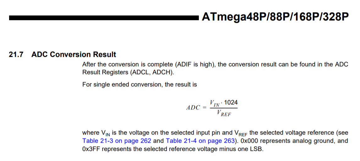
The formula from the datasheet is: \(ADC = \frac{V_{in} \times 1024}{V_{ref}}\), where \(V_{ref}\) is the reference voltage (typically 5V on the Uno) and \(ADC\) is the 10-bit digital result (0–1023).
For most practical purposes, dividing by 1023 or 1024 won’t matter. :) If you want to estimate the voltage at the center of each ADC bin rather than the bottom edge, you can add 0.5 to the analogRead value before dividing by 1024—but again, for 10-bit physical computing applications, this level of precision is rarely needed.
For more on this hotly debated issue, read:
-
ADC Conversion on the Arduino, by Nick Gammon
-
Precise Voltage Measurement with Arduino, by John Errington
How fast can we sample a sensor with analogRead()?
When working with analog sensors, it is important to distinguish between the limitations of the standard Arduino software and the true capabilities of the microcontroller hardware:
-
The Arduino Software Limit: By default, the standard Arduino analogRead() function is configured for safety and stability rather than pure speed. It takes approximately 104 μs to execute, which limits your practical sampling rate to roughly 9,600 samples per second.
-
The True Hardware Capability: According to Section 23 of the ATmega328P datasheet, the raw hardware is actually capable of conversion times between 65 and 260 μs, supporting up to 15,000 samples per second at maximum 10-bit resolution.
For reading basic sensors or potentiometers, the default Arduino software speed is more than sufficient. However, if you are trying to sample higher-frequency signals like audio, keep in mind that you can bypass the default analogRead() settings to unlock the hardware’s full 15kSPS potential.
What does delay() actually do?
As you might expect—given our warnings about avoiding overuse of delay(unsigned long ms)—the delay code consists of a while loop that simply waits for the given amount of delay time to pass. There is a yield() call within the while loop but this is, by default, an empty function—though you could implement it to create a “real cooperative scheduler.” The code for yield() is here.
The delay(unsigned long ms) function is found in wiring.c and is, in its entirety, copied below:
void delay(unsigned long ms)
{
  uint32_t start = micros();

  while (ms > 0) {
    yield();
    while ( ms > 0 && (micros() - start) >= 1000) {
      ms--;
      start += 1000;
    }
  }
}
How does digitalWrite() work internally?
When you call digitalWrite(3, HIGH), what actually happens at the hardware level? The AVR microcontrollers control their GPIO pins through port registers—special memory-mapped bytes where each bit corresponds to a physical pin.
How these pins map to the registers depends entirely on your board:
- Arduino Uno (ATmega328P): The mapping is very clean. Digital pins 0–7 map to
PORTDand pins 8–13 map toPORTB. - Arduino Leonardo (ATmega32U4): Because of the built-in USB hardware, the pin mapping is scattered. For example, pins 0–4 map to various bits on
PORTD, pin 5 is onPORTC, and pin 7 is onPORTE.
The digitalWrite() function (found in wiring_digital.c) does the following:
- Looks up which port register and bit correspond to the given pin number (using a lookup table).
- Disables interrupts briefly to prevent race conditions.
- Sets or clears the appropriate bit in the port register.
- Re-enables interrupts.
This lookup and safety logic is why digitalWrite() is relatively slow (~4-5 μs per call). For performance-critical code, experienced programmers bypass it and manipulate the port registers directly. For example, on an Uno, PORTD |= (1 << 3); sets Pin 3 HIGH in just two clock cycles (~125 ns at 16 MHz, via the AVR sbi instruction)—roughly 30-40x faster.
For our introductory lessons, digitalWrite() is perfectly fast enough. But it’s good to know what’s happening under the hood!
How does analogWrite() and PWM work internally?
As covered in L4: Fading an LED, analogWrite() doesn’t produce a true analog voltage—it generates a PWM waveform. But how does the hardware create this waveform?
Arduino boards use hardware Timers built into the microcontroller to generate PWM. When you call analogWrite(pin, value), the Arduino core code configures the timer associated with that pin for PWM mode and sets a compare match register to your 8-bit value (0–255). The hardware then continuously counts from 0 to 255; when the count is below your value, the pin is HIGH, and when above, it’s LOW. This happens entirely in the background, freeing up the CPU.
The timers and available PWM pins differ depending on your board:
Arduino Uno (ATmega328P) The Uno has three hardware timers driving 6 PWM pins. | Timer | PWM Pins | Frequency | Notes | | :— | :— | :— | :— | | Timer0 | 5, 6 | ~980 Hz | Also used by millis() and delay() | | Timer1 | 9, 10 | ~490 Hz | 16-bit timer | | Timer2 | 3, 11 | ~490 Hz | 8-bit timer |
Arduino Leonardo (ATmega32U4) The Leonardo has four usable hardware timers driving 7 PWM pins. | Timer | PWM Pins | Frequency | Notes | | :— | :— | :— | :— | | Timer0 | 3, 11 | ~980 Hz | Also used by millis() and delay() | | Timer1 | 9, 10 | ~490 Hz | 16-bit timer | | Timer3 | 5 | ~490 Hz | 16-bit timer | | Timer4 | 6, 13 | ~980 Hz | High-speed 10-bit timer (clocked by a PLL) |
Because Timer0 is responsible for millis() and delay(), altering its configuration to change your PWM frequency on pins 5 and 6 (Uno) or pins 3 and 11 (Leonardo) will break your timekeeping functions.
Writing Blinky in Bare-Metal C
If you bypass the Arduino framework entirely, you can write code directly for the AVR microcontroller using standard C. This is often called “bare-metal” programming. It reveals the hidden main() function and replaces user-friendly functions like pinMode() and digitalWrite() with direct hardware register manipulation.
Here is what a standard “Blinky” sketch looks like in bare-metal C for the Arduino Uno (ATmega328P). On the Uno, the built-in LED (Pin 13) is hardwired to bit 5 of Port B (PB5). According to Section 13.2.1 of the ATmega328P datasheet, the DDxn bit in the Data Direction Register (DDRx) selects the pin’s direction, and the PORTxn bit in the Data Register sets the output logic level.
#ifndef F_CPU
#define F_CPU 16000000UL // 16 MHz clock speed
#endif

#include <avr/io.h>      // Hardware register definitions
#include <util/delay.h>  // _delay_ms() function

int main(void) {
    // 1. Setup: Configure PB5 (Pin 13) as an output
    DDRB |= (1 << PB5);

    // 2. Loop: The equivalent of the Arduino loop()
    while (1) {
        // Toggle the state of PB5 using bitwise XOR
        PORTB ^= (1 << PB5);

        // Wait for 1000 milliseconds
        _delay_ms(1000);
    }

    // never reached
    return 0;
}
If we want to run this exact same bare-metal Blinky on an Arduino Leonardo (ATmega32U4), the code has to change. Because of the Leonardo’s internal USB hardware, the built-in LED (Pin 13) is wired to bit 7 of Port C (PC7).
#ifndef F_CPU
#define F_CPU 16000000UL
#endif

#include <avr/io.h>
#include <util/delay.h>

int main(void) {
    // 1. Setup: Configure PC7 (Pin 13) as an output
    DDRC |= (1 << PC7);

    // 2. Loop
    while (1) {
        // Toggle the state of PC7
        PORTC ^= (1 << PC7);
        _delay_ms(1000);
    }

    // never reached
    return 0;
}
The Takeaway: Hardware Abstraction
This comparison perfectly illustrates the concept of Hardware Abstraction—the core reason the Arduino framework exists.
When you write digitalWrite(13, HIGH), the exact same Arduino sketch works on both the Uno and the Leonardo without you having to change a single line of code or read a datasheet. The Arduino software handles the translation in the background, figuring out that “Pin 13” means PB5 on the Uno and PC7 on the Leonardo.
The tradeoff is speed. digitalWrite() takes about 4-5 microseconds to do its safety checks and look up those pin mappings. In contrast, bare-metal port manipulation (PORTB ^= (1 << PB5)) compiles down to a single machine instruction that executes in just a few clock cycles (~125 nanoseconds). Arduino gives you cross-compatibility and ease of use, while bare-metal C gives you maximum performance and complete control.
How does millis() work?
The millis() function, which we use extensively in L8: Rate Blinking LEDs, returns the number of milliseconds since the Arduino started running. But how does it keep track of time?
The answer is Timer0 overflow interrupts. Timer0 is an 8-bit counter that counts from 0 to 255 at a rate determined by the CPU clock and a prescaler. On the Uno (16 MHz clock, prescaler of 64), Timer0 overflows approximately every 1.024 ms. Each time it overflows, a hardware interrupt fires and increments an internal counter. The millis() function simply reads this counter.
You can see the implementation in wiring.c—look for the TIMER0_OVF_vect interrupt service routine (ISR) and the millis() function.
A few important implications:
millis()has a resolution of approximately 1 ms, not exactly 1 ms (because 1.024 ms ≠ 1 ms). The Arduino core includes correction logic to compensate, but tiny drift can accumulate over very long periods.- Since
millis()relies on interrupts, it will not advance inside an ISR or while interrupts are disabled (vianoInterrupts()). - As noted in L8,
millis()overflows back to zero after approximately 49.7 days. Usingunsigned longarithmetic handles this correctly.
For microsecond resolution, use micros(), which has ~4 μs resolution on the Uno and overflows after ~70 minutes.
How does the Arduino Uno ADC work exactly?
To convert analog signals to digital, the ATmega328 uses a successive approximation ADC, which Wikipedia nicely summarizes as: “a type of analog-to-digital converter that converts a continuous analog waveform into a discrete digital representation via a binary search through all possible quantization levels before finally converging upon a digital output for each conversion.”
As Charles Platt explains in Encyclopedia of Electronic Components Volume 3 (Maker Media, 2016), a successive approximation converter works by comparing the input voltage against a DAC output using a single comparator. It determines the digital value one bit at a time, from the most significant to the least significant bit, storing each result in a successive approximation register (SAR). This approach can achieve high resolution (many bits) at the cost of lower conversion speed compared to other ADC architectures.
What is the analog input pin resistance on the ATmega328?
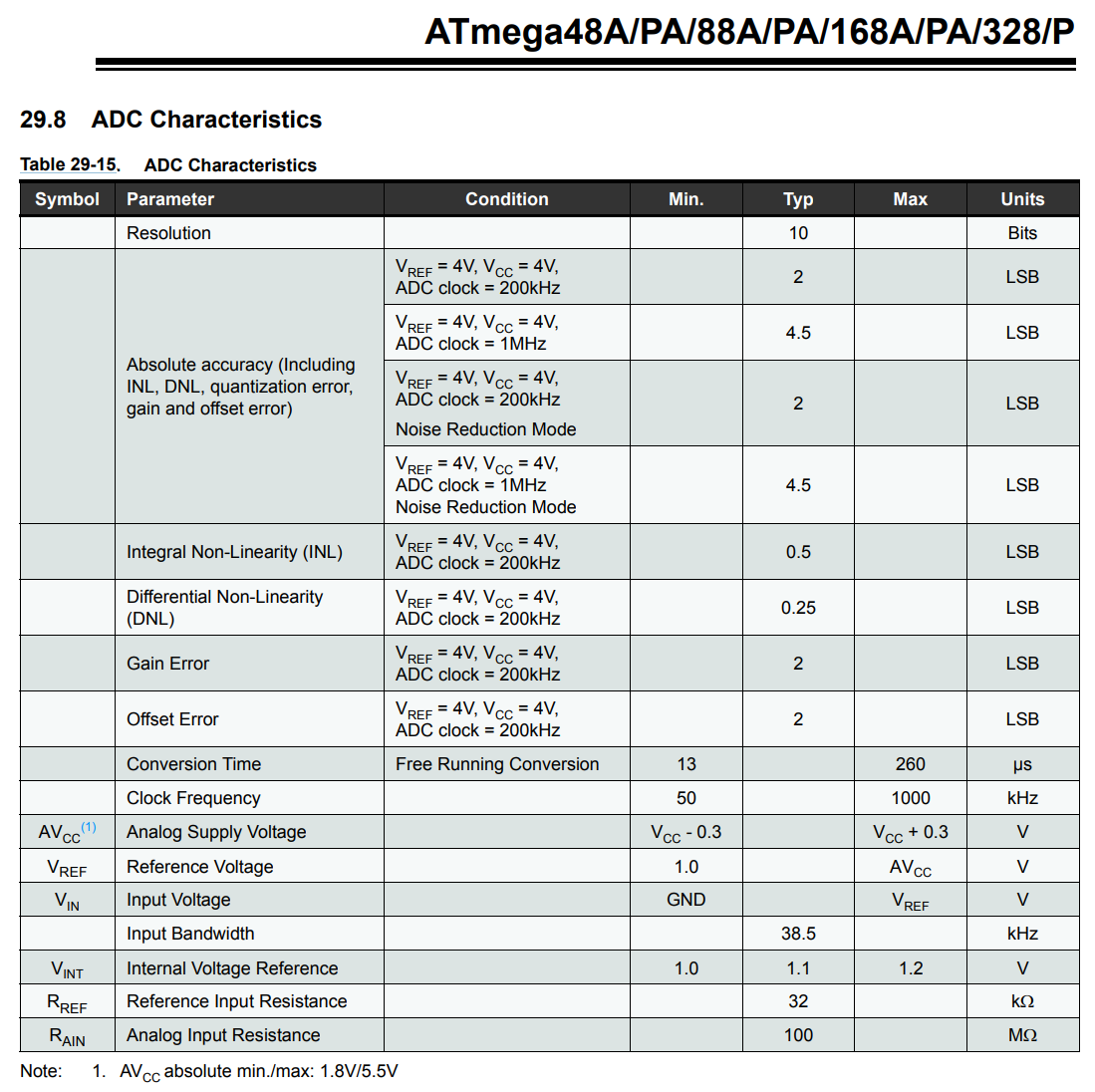
The ATmega328 datasheet says that the analog input resistance is 100 megohms:
Source impedance and analog pin “ghosting”
While the analog input resistance is very high (100 MΩ), there’s an important practical limitation that trips up many students. The ADC uses an internal sample-and-hold capacitor that must fully charge to the input voltage before each conversion. Section 23.6.1 of the ATmega328P datasheet specifies that the ADC is optimized for analog signals with an output impedance of 10 kΩ or less. (This same 10 kΩ limit applies to the Leonardo’s ATmega32U4 chip).
If you use high-value resistors in a voltage divider (e.g., a 1 MΩ photoresistor with a 1 MΩ fixed resistor), the sample-and-hold capacitor won’t charge fast enough, and you may see readings from one analog pin “bleed” into the next pin you read—a phenomenon sometimes called “ghosting.” This is especially noticeable when rapidly switching between multiple analogRead pins.
If you encounter ghosting, you can add a small delay between
analogReadcalls on different pins, or do a “dummy read” on each pin (read it twice and discard the first result) to give the capacitor time to settle. Better yet, keep your source impedance below 10 kΩ.
References
- Arduino Uno pin current limits, StackExchange
- ADC Conversion on the Arduino, Nick Gammon
- The Arduino ADC, John Errington
Secrets of Arduino PWM
For a deep dive into how PWM works on the ATmega microcontrollers, including how to change PWM frequencies and use different timer modes, see the official Secrets of Arduino PWM tutorial.
Reverse Polarity Protection: Uno vs. Leonardo
If you accidentally plug a power supply in backward, how does the Arduino protect itself? It depends on the board!
The Arduino Uno (Series Protection) The Uno uses an M7 diode in series between the barrel jack’s positive terminal and the VIN pin. If you connect power backward, the diode simply blocks the current, protecting the board. The tradeoff is a ~0.7V forward voltage drop across the diode, and the total current you can draw from VIN is limited to the diode’s maximum rating (typically 1A).
The Arduino Leonardo (Shunt Diode) The Leonardo connects the barrel jack directly to the VIN pin. However, it has a diode wired in parallel between GND and VIN that conducts under reverse-polarity conditions, acting as a shunt.
- The Advantage: There is no 0.7V voltage drop, and the current limit is dictated only by the PCB traces. This makes the Leonardo slightly better for driving high-current loads (like servos) directly from the
VINpin. - The Danger: If you connect a reverse-polarity supply, this parallel diode intentionally shorts the circuit to ground. If you are using a power supply with overcurrent protection (like a fused wall adapter), it will safely trip. However, if you use an unprotected high-current source like a AA or 9V battery pack, the diode will take the full brunt of the short, overheat, and fail—often destroying the 5V voltage regulator and the rest of the board in the process.
Always double-check battery polarity if using external battery packs via the barrel jack on the Arduino Leonardo!
How Does Reverse Polarity Happen?
A barrel jack only plugs in one way, so how can polarity get reversed? The mistake almost always happens before the plug reaches the board.
Center-negative power adapters. The Arduino expects a center-positive barrel plug (the inner pin is +, the outer sleeve is GND). However, many consumer devices use center-negative adapters—most notably guitar effect pedals, which have standardized on center-negative 9V. If you grab a spare 9V adapter from a music setup, it will fit the Arduino’s barrel jack perfectly but deliver reversed polarity. Always check the polarity symbol printed on the adapter (a small diagram showing which conductor is +) before plugging in.
Screw-terminal barrel jack adapters. Many starter kits include a barrel jack breakout with a screw-terminal block for connecting bare wires from a battery snap or battery pack. It is very easy to accidentally screw the red wire into the − terminal and the black wire into the + terminal, especially when the terminal labels are small or hard to read.
Wiring directly to VIN and GND headers. Students sometimes power the board by plugging jumper wires from a battery pack directly into the header pins. If you swap the wires—red into GND, black into VIN—you get reverse polarity that bypasses all on-board protection, even the Uno’s series diode. Both boards are equally vulnerable in this case.
When in doubt, use a multimeter. Before connecting any unfamiliar power source, use a multimeter set to DC voltage to confirm which wire or terminal is positive. It takes ten seconds and can save your board.