Lesson 4: Potentiometers
Table of Contents
- Potentiometers: a refresher
- Materials
- Making an LED dimmer with a potentiometer
- Intro to analog input
- Hooking up variable resistors with microcontrollers
- Exercises
- Lesson summary
- Next Lesson
In this lesson, we’ll refresh our memories about potentiometers, learn a bit about multimeters, and then introduce the concept of analog input and hook-up potentiometers as voltage dividers to Arduino! Similar to the buttons lesson, we are going to use potentiometers on their own before learning how to use them with microcontrollers.
A video demonstration of a trimpot hooked up to analog input A0 on the Arduino. The A0 value is graphed on an OLED display in real-time. The code is available here.
In this lesson, you will learn:
- How potentiometers work as both variable resistors (rheostats) and voltage dividers
- How to use a multimeter to measure current in a circuit
- What analog input is and how it differs from digital input
- How the Arduino’s analog-to-digital converter (ADC) works and what 10-bit resolution means
- Why variable resistors must be wired as voltage dividers to work with microcontrollers
- How to use
analogRead()to read analog input from a potentiometer
Potentiometers: a refresher
In our Intro to Electronics lessons, we learned about potentiometers. Recall that a potentiometer (or pot) is a three-terminal resistor with a sliding or rotating contact that can be used to dynamically vary resistance.
Video. This animation shows how the wiper can be used to vary resistance in a rotary potentiometer. The figure on the right is the formal electrical symbol. Animation by Jon Froehlich. Created in PowerPoint.
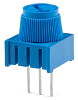
Potentiometers are common electronic components found in everything from volume controls to analog joysticks. In our UW courses, we often provide 10kΩ potentiometers in our kits like the 10K panel mount potentiometer and 10K trim potentiometer, shown below.
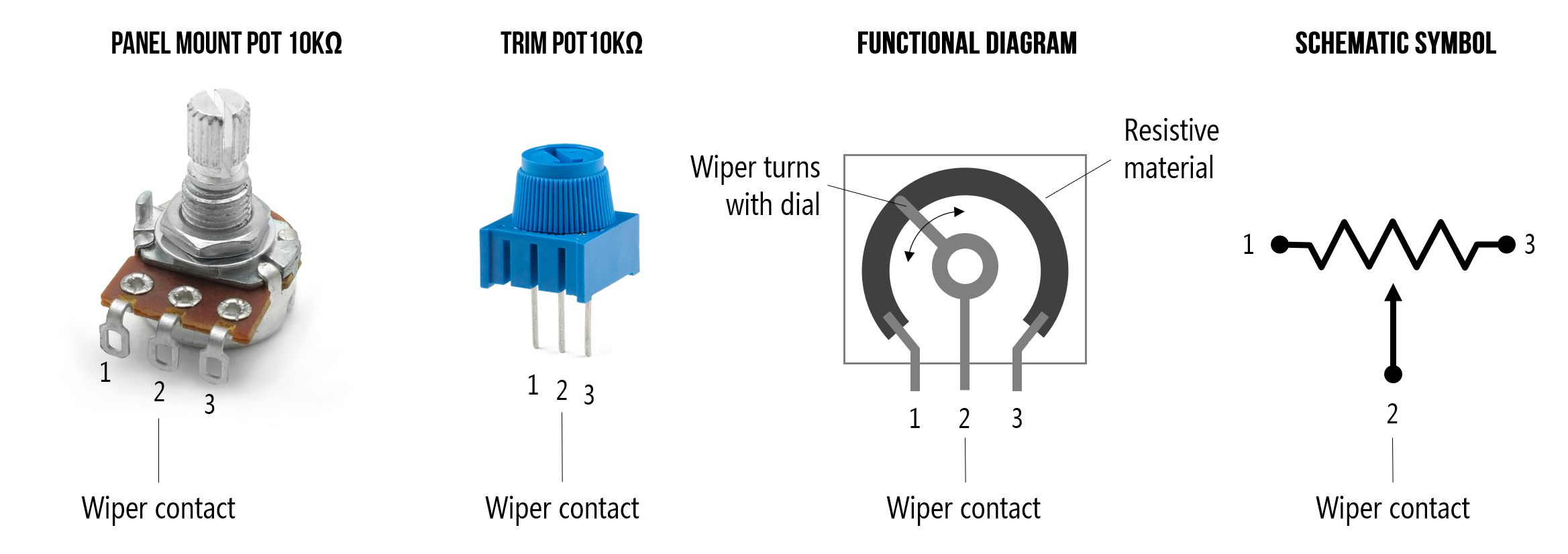 Figure. Two example potentiometers commonly included in our hardware kits: a 10kΩ panel mount and a 10kΩ trim potentiometer.
How does a potentiometer work?
Potentiometers have three legs: the resistance between the outer two legs (Leg 1 and Leg 3) will not vary. For example, if you are using a 10kΩ potentiometer, then the resistance between Legs 1 and 3 will always be 10kΩ regardless of wiper position (Leg 2). If you’re using a 1kΩ potentiometer, then the resistance between Legs 1 and 3 will be 1kΩ, and so on.
The power of a potentiometer is in that middle leg (Leg 2) whose resistance varies depending on the potentiometer’s sliding or rotating contact (the wiper) position. It may help to think of a potentiometer as containing two interdependent resistors \(R_1\) and \(R_2\) that always sum to \(R_{Total}\) (where \(R_{Total}\) is the potentiometer’s total value like 1kΩ or 10kΩ). As you move the slider contact, \(R_1\)’s resistance will increase as \(R_2\)’s resistance decreases. See animation below.
Video. Animation by Jon Froehlich. Created in PowerPoint.
Using two multimeters set to measure resistances across both Legs 1-2 and 2-3, we can examine this behavior directly. Notice how as you move the wiper, the resistance across Legs 1 and 2 (\(R_{1}\)) and Legs 2 and 3 (\(R_{2}\)) proportionally change but always sum to \(R_{total}\). We are using a 10kΩ potentiometer so \(R_{total}=10kΩ\)
Video. Using two multimeters, we can examine how the resistances change between Legs 1-2 and 2-3. Note that the resistance between the outer legs (Legs 1-3) will always sum to the potentiometer’s total value. In this case, we’re using a 10kΩ, so it would sum to 10kΩ. Try it out on Tinkercad here.
Potentiometers as variable resistors vs. voltage dividers
There are two common ways to use a potentiometer:
- As a variable resistor or rheostat—where you only hook up two legs (the wiper leg and an outer leg)
- And as a voltage divider where we hook up all three legs with the middle leg connected to the analog input of our microcontrollers.
To use these two-leg variable resistors with a microcontroller, we will need to add an additional fixed resistor to create a voltage divider. We’ll show you how to do that in our next lesson.
Below, we are going to focus on using a potentiometer first as a two-legged variable resistor and then as a voltage divider with our Arduino.
Materials
Let’s start building with the potentiometer! We’ll need the following materials:
| Breadboard | Arduino | LED | Resistor | Trimpot |
|---|---|---|---|---|
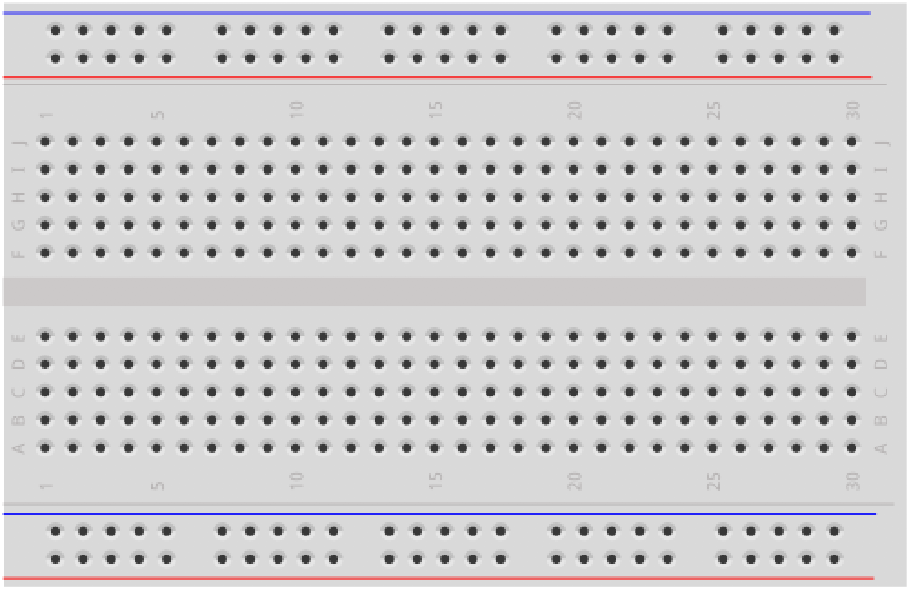 | 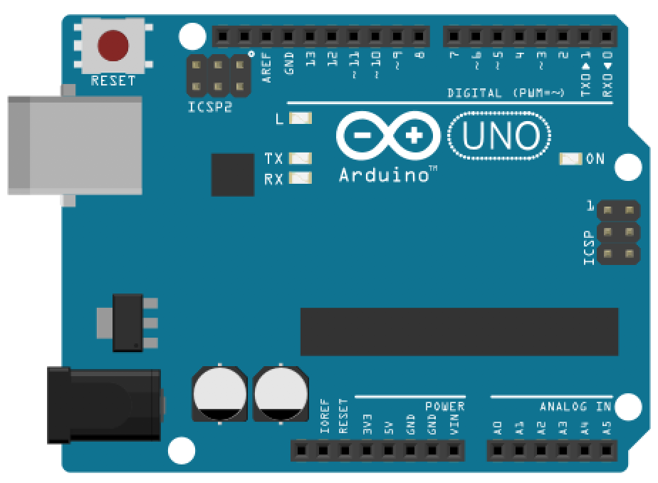 | 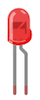 | 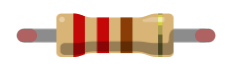 |  |
| Breadboard | Arduino Uno, Leonardo, or similar | Red LED | 220Ω Resistor | 10kΩ Trimpot |
Making an LED dimmer with a potentiometer
For our first making activity, we’re going to create a potentiometer-based LED dimmer. We won’t yet be using an Arduino. This will be a pure electrical circuit (no microcontrollers for a bit!).
A Tinkercad prototype
Let’s build a prototype in Tinkercad Circuits before building a physical prototype. While similar to the activity in Variable Resistors, we add in uses of Tinkercad’s multimeter to check our circuits and also emphasize correct and incorrect hookups. Moreover, doing this activity before the Arduino-based one will help reinforce differences between using a potentiometer simply as a two-legged variable resistor and as a three-legged voltage divider.
Still, if you feel confident in your understanding of potentiometers as two-leg variable resistors, then feel free to skip to the Intro to Analog Input part of this lesson!
Step 1: Build the potentiometer-based LED dimmer
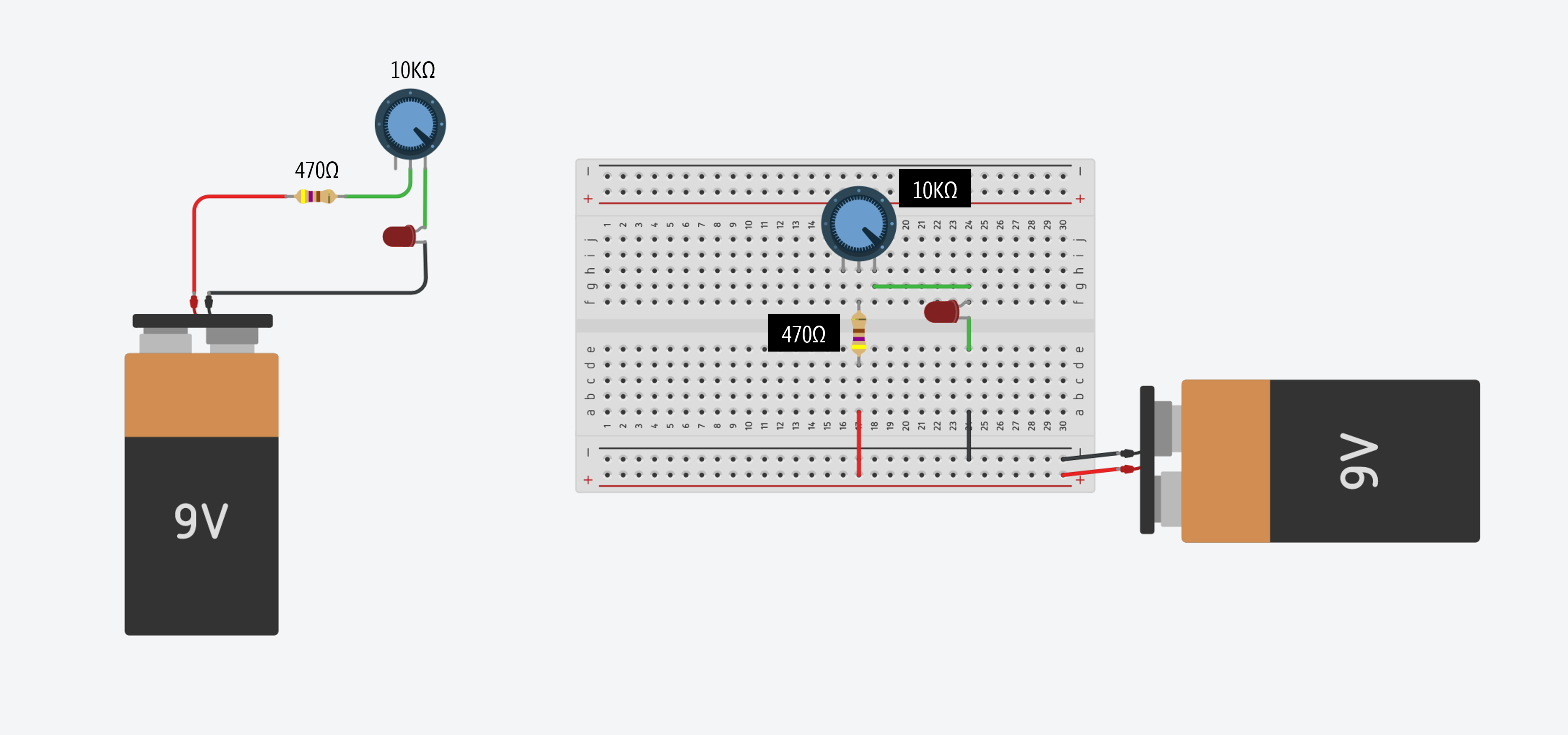
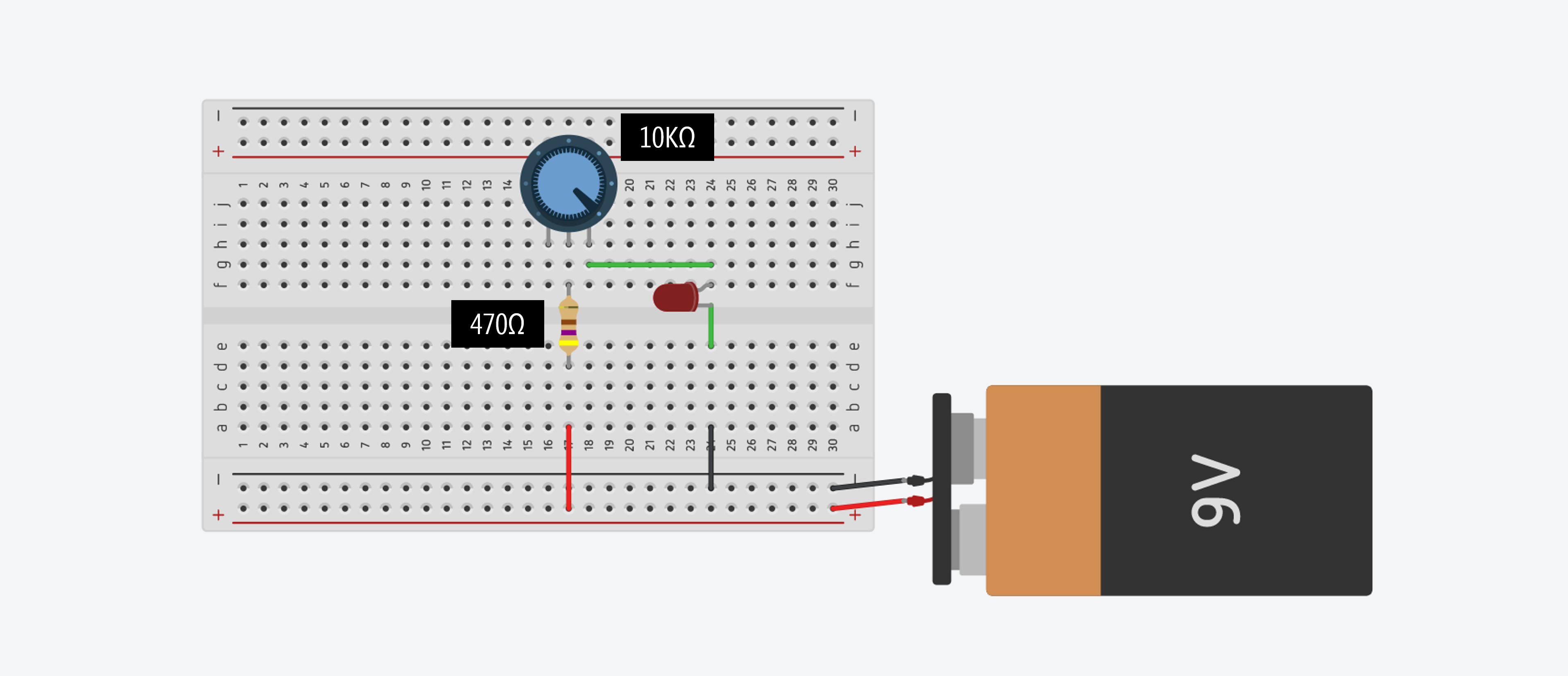
First, let’s build the potentiometer-based LED dimmer. In Tinkercad, you could make your dimmer with or without a breadboard (both are shown in the figure below). Let’s prototype something we would actually make in real life, so go with the breadboarded version:
 You can access these Tinkercad circuits here (no breadboard) and here (with breadboard).
Important: Recall that it’s important to include that additional resistor because many potentiometers, including those provided in your hardware kits, go all the way down to 0Ω. If you don’t have that “backup” current-limiting resistor, you will blow your LED if the potentiometer dial is set to 0Ω. (Indeed, try it out in Tinkercad and see what happens—kablooey!)
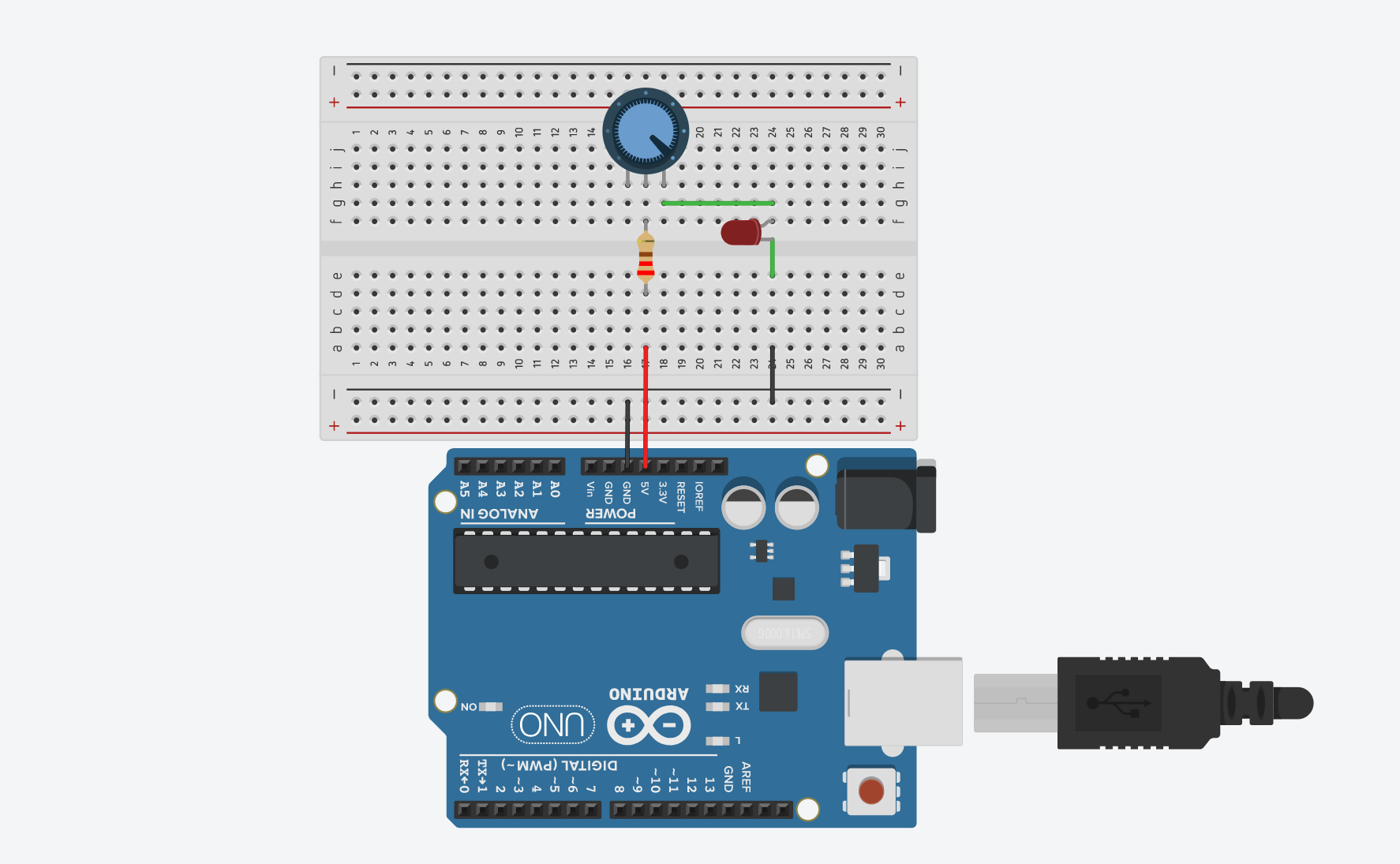
Here’s one possible wiring for a potentiometer-based LED fading circuit:
Step 2: Now simulate your circuit
Once you’re done, try simulating your circuit. Click the “Start Simulation” button (see animation below):
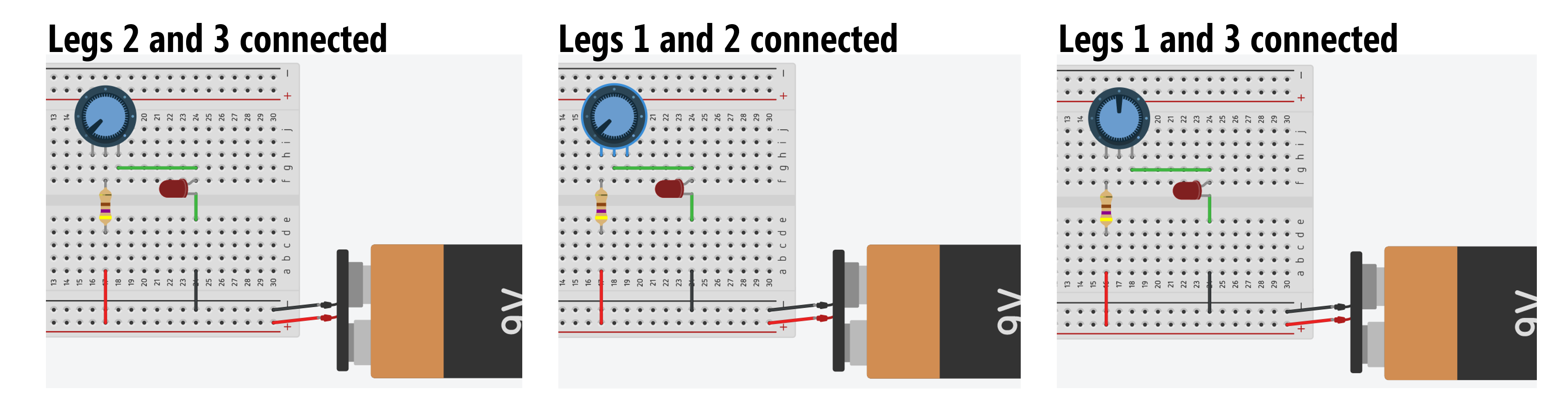
In the circuit above, we hooked up legs 2 and 3 of the potentiometer. What happens if you, instead, hook up legs 1 and 3 or 1 and 2? Try it!
Add ammeter to Tinkercad prototype
To help us observe the effect of the potentiometer’s wiper position on the total current in our circuit, we can use Tinkercad’s multimeter tool. A multimeter can be used for a variety of circuit measurements, including measuring resistance (ohmeter), current (ammeter), voltage (voltmeter), and testing for short circuits (continuity testing).
How to measure current with a multimeter
Voltmeters measure voltage in parallel. Ammeters measure current in series (ammeter comes from Amperage meter). See the wiring diagram below.
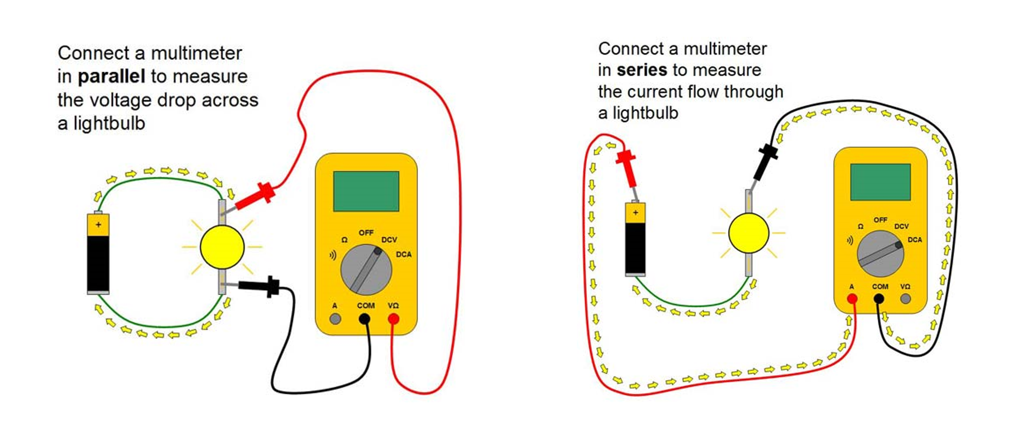 Image from this great “Science Buddies” tutorial on using multimeters.
To help us think about and remember how to measure current, we like to return to our water analogies from our Intro to Electronics lessons: think of the ammeter as if it’s a mechanical water flow meter (aka a turbine) that must be in-line within a pipe to measure water flow. An ammeter must be “in line” to measure current—you must rewire your circuit such that current is forced through your ammeter (just like water flowing through a turbine in a pipe).
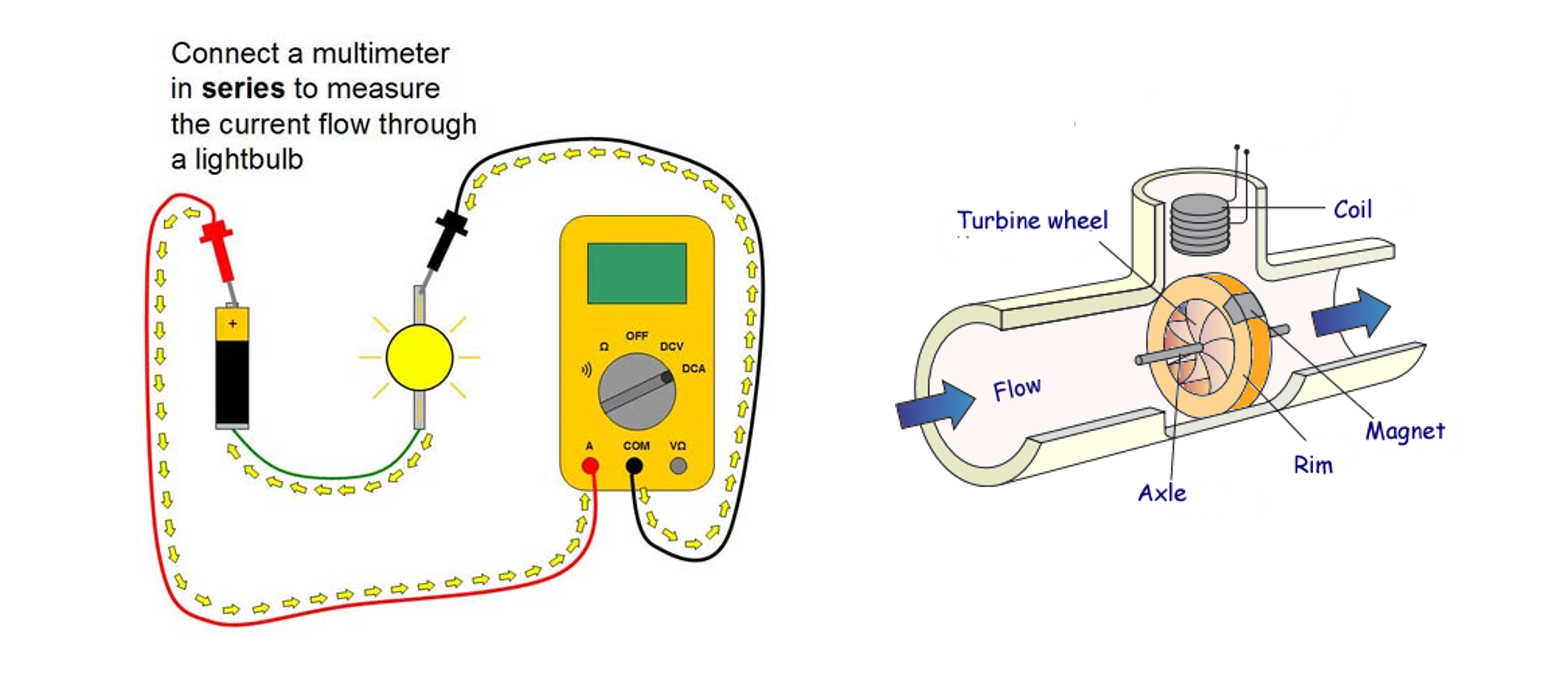 Image adapted from “Science Buddies”.
Updated Tinkercad circuit with ammeter
Because there is only one path for the current to flow in this circuit (no branches), we could hook up the ammeter at any in-series location—for example, in between the potentiometer and LED or the resistor and potentiometer. We just selected a position that I found convenient.
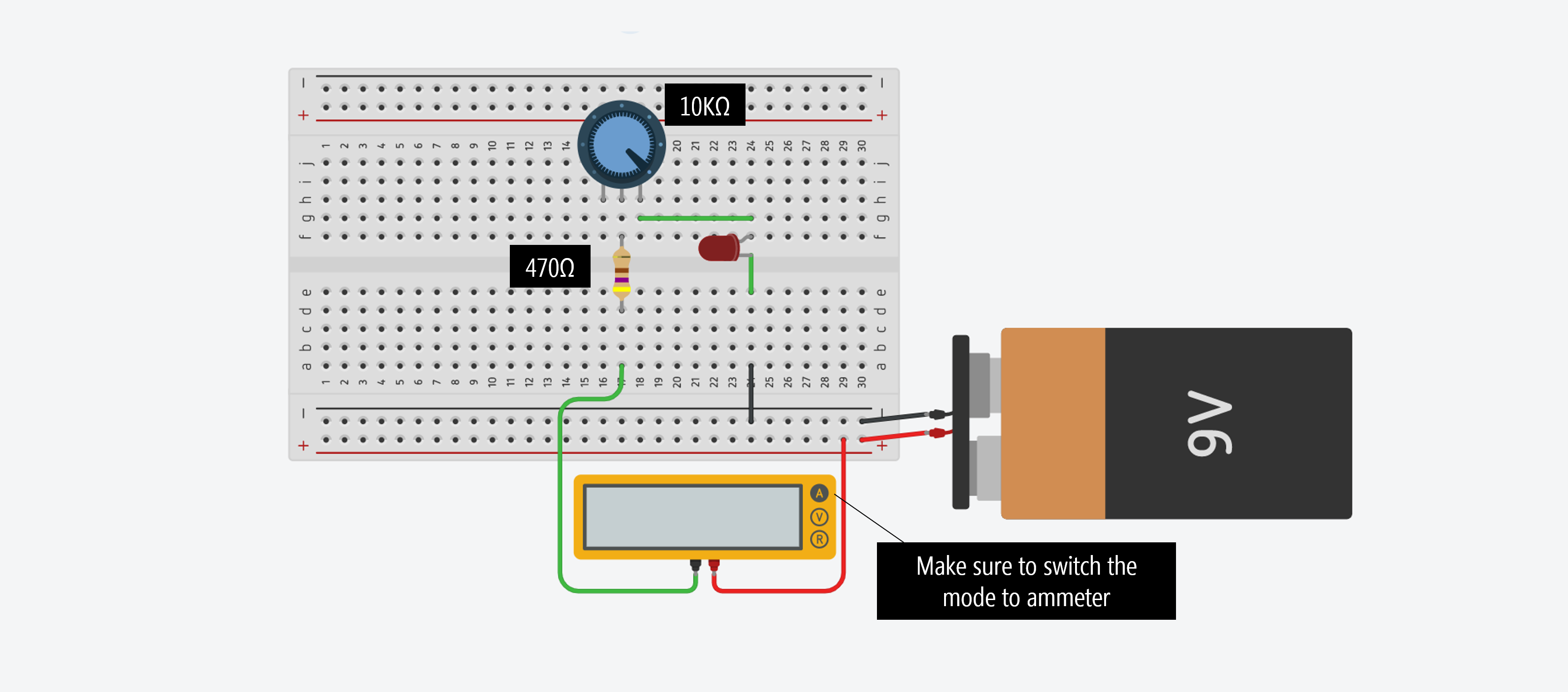
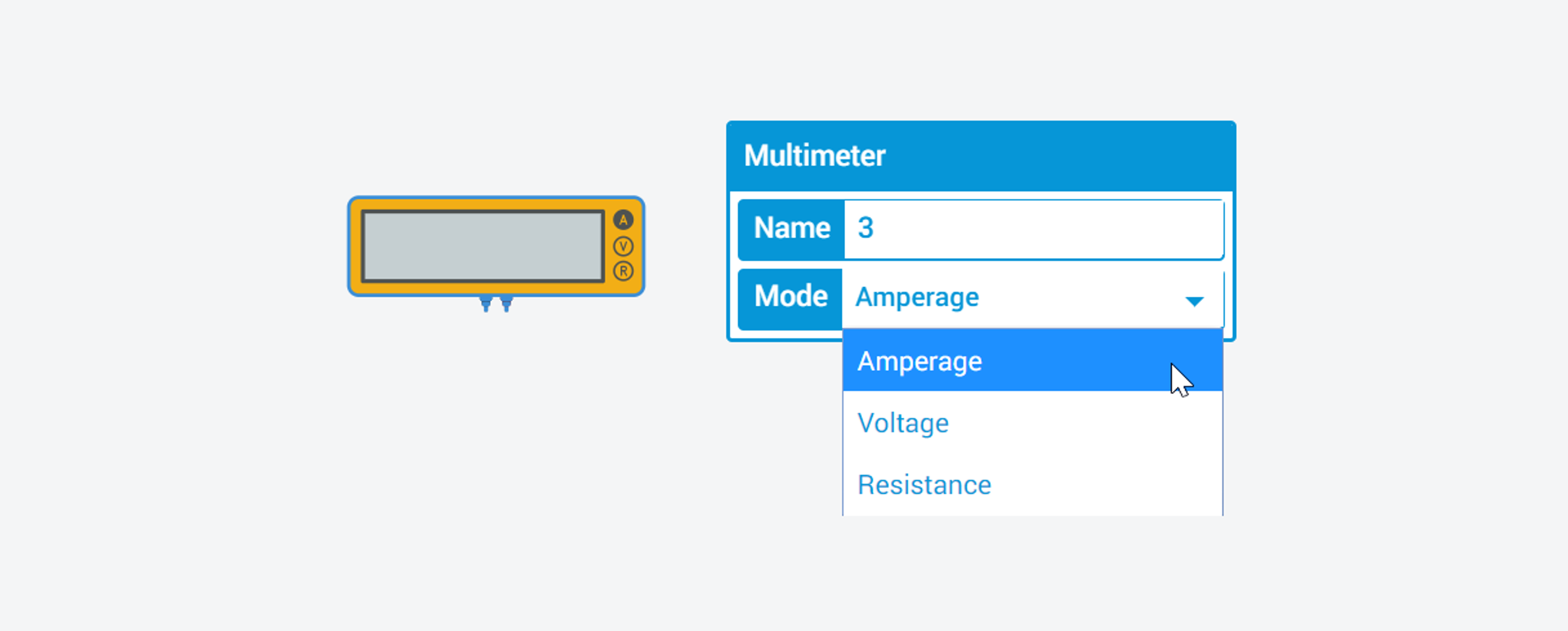
Note: when you drag over a multimeter, make sure you click on it and change the mode to ammeter to measure current (select Amperage).
Tinkercad simulation with ammeter
Here’s our circuit with the ammeter running in the simulator. Does the simulation match your expectations?
Because we have Leg 2 hooked to the positive voltage source and Leg 3 as our “output”, as we move the wiper from left-to-right, there is a smaller amount of resistance and an increase in current. You’ll notice a jump in current when the \(V_f\) condition of the LED is met (recall the LED IV curves from our LED lesson).
Before moving on, play around with the multimeter in Tinkercad. You can add multiple voltmeters and ammeters to your Tinkercad circuits, which is a handy way to learn how voltages and currents are working, verify Ohm’s Law, and double check your mental model of a circuit before expending effort actually building it.
Circuit simulation in CircuitJS
We also made this circuit in CircuitJS, which offers a far more powerful and feature-rich simulation compared with Tinkercad but is still relatively accessible to novices. We like it because it shows an illustrative animation of current (just like some of the animations from our previous lessons that we’ve manually made).
There are two differences in this circuit compared to the Tinkercad one above. First, we used a 1kΩ potentiometer rather than a 10kΩ but the general effect is the same. Second, here we have Leg 1 hooked up towards the positive voltage source and Leg 2 as our “output”, so resistance is minimized when the dial is all the way left (it was the opposite for our Tinkercad circuit).
Let’s build it for real
OK, let’s build this thing for real with our hardware parts.
Because not all of us have access to a 9V battery + snap connector (or alligator clips) to easily interface with our breadboards, we can again use our Arduino for a power source (just like we did in our very first Arduino lesson: LED On).
Given that the Arduino supplies 5V rather than 9V, we can replace our 470Ω resistor with a smaller resistor like a 220Ω (but you can certainly use a 470Ω or 680Ω if you’d like—remember, this is a backup resistor for when the potentiometer’s wiper resistance goes to 0Ω).
 You can play with this Tinkercad circuit here.
Workbench video of our trimpot dimmer
Here’s a workbench video of our trimpot circuit where the potentiometer is simply a two-legged variable resistor and we’re using the Arduino only as a 5V voltage source:
Whew, we did it!
By now, you should feel pretty confident with using a potentiometer as a variable resistor; however, using potentiometers (or any variable resistor) with a microcontroller requires a different circuit configuration as you’ll see below.
Intro to analog input
In our previous lessons, we learned about digital output, then analog output, and finally digital input. Now, it’s time for the last frontier: analog input!
So, what’s analog input?! The world—in all its beauty and complexity—is analog. It’s not simply HIGH and LOW but everything in between. How can we sense and access that complexity?
Analog input!
More formally, just like analog output enabled us to write out voltages between 0V and 5V, analog input enables us to read voltages between 0V and 5V. How does this work? Via an ADC.
Video. While digital input is simply HIGH (5V) or LOW (0V), analog can be anywhere in between. Our ability to sense gradations in the voltage signal is based on the resolution of the analog-to-digital converter. In the case of the Arduino Uno and Leonardo, this is 10 bits.
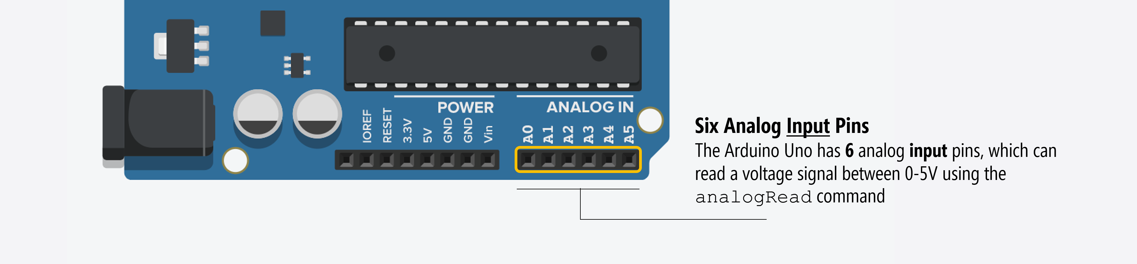
Analog input pins
The Arduino Uno has six analog inputs (A0-A5), which can be read using analogRead(int pin). The analogRead function reads voltage values between 0 and the Arduino’s operating voltage (5V on the Uno and Leonardo) and converts this into integer values between 0 and 1023.
Often, students get confused between the analog output pins (which use PWM, see Fading an LED) and the analog input pins. They are different.
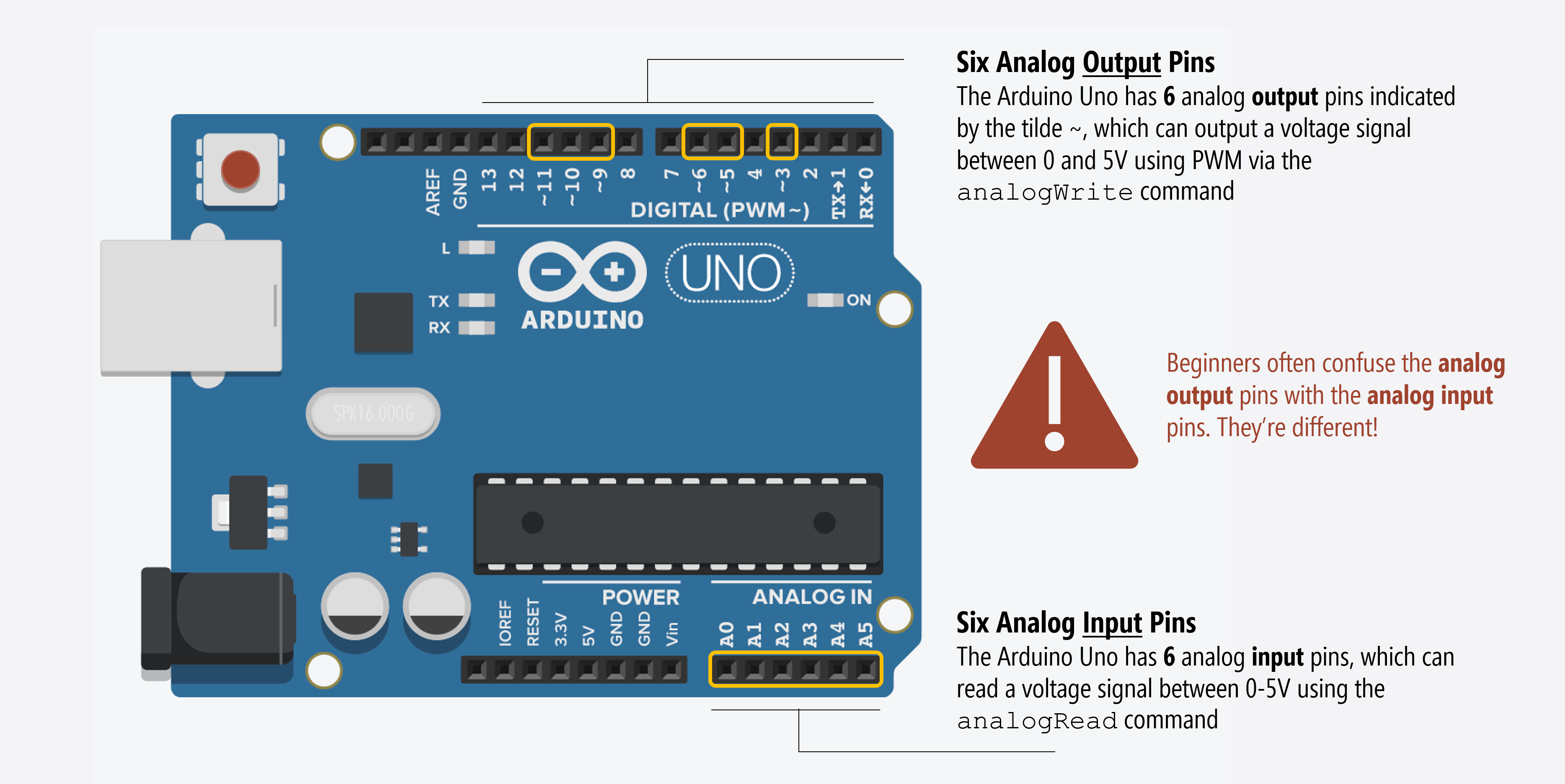
You can access the analog input pins using A0, A1 … AN. For example, analogRead(A0) to read analog input on pin 0. The Arduino Uno has six analog input pins: A0 - A5.
Arduino Leonardo has 12 analog inputs
At first glance, the Arduino Leonardo appears to have just six analog inputs (like its close sibling the Arduino Uno). But once again, the PCB silkscreening throws us off!
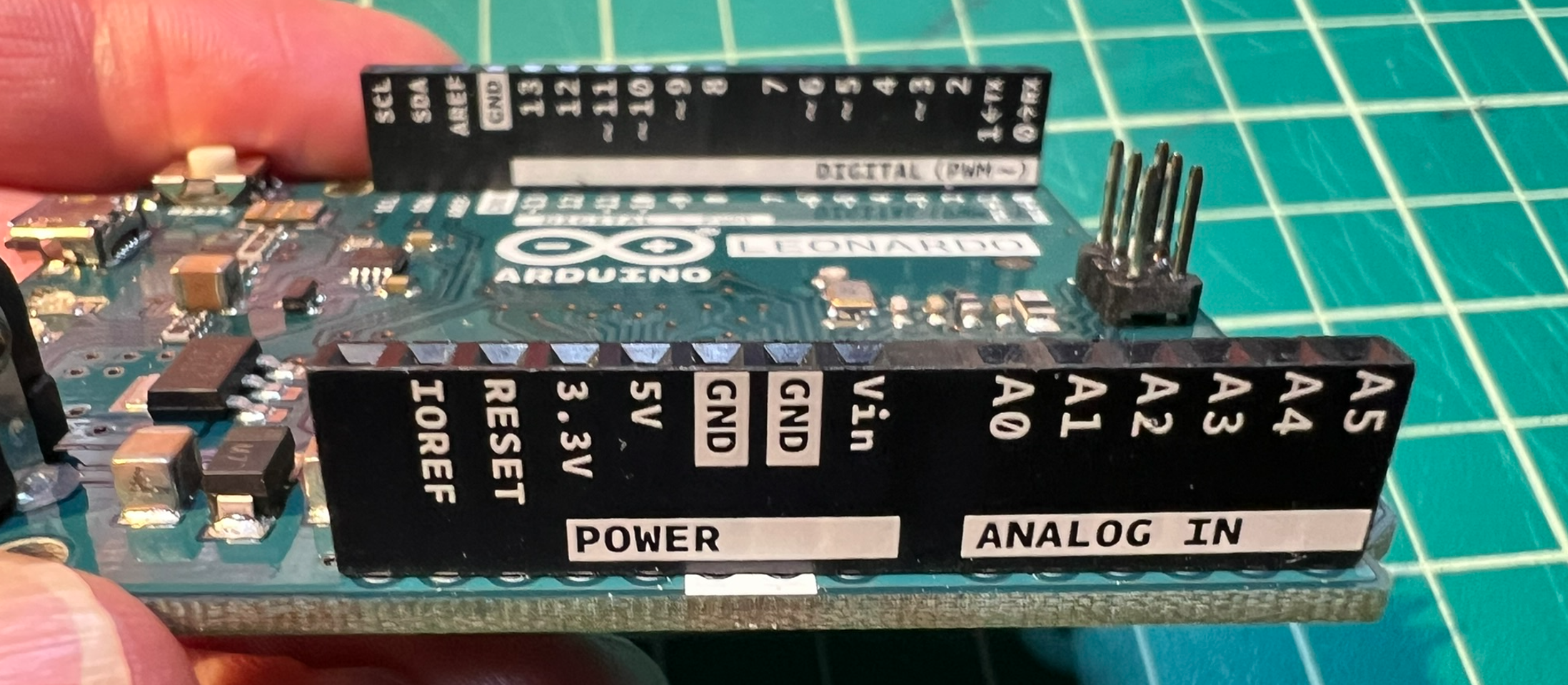
In fact, if you flip over the Leonardo, you’ll discover additional white silkscreening, which reveals six more analog inputs (for a total of 12)
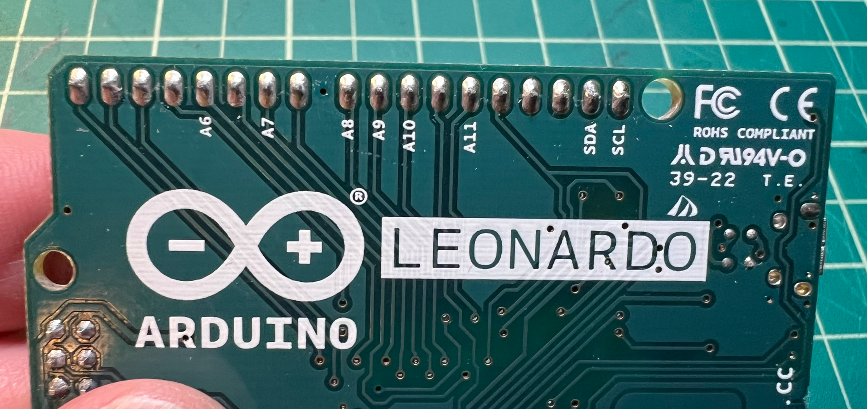
You can access these by specifying A6 - A11 in your code. For example:
int analogVal = analogRead(A6); // A6 is same as D4
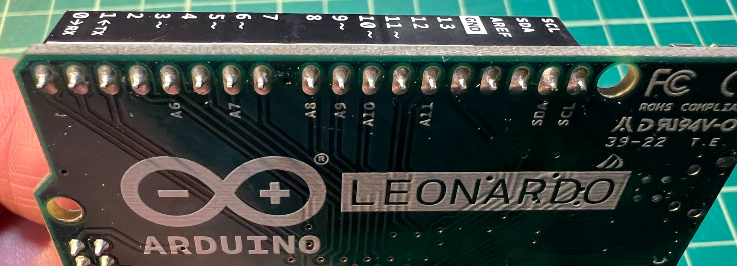
Another view of the back of the Arduino Leonardo board showing the additional analog input pins.
The mapping between analog input pins and digital I/O pins are described in the docs:
| Analog Input Pin | Digital I/O Pin |
|---|---|
| A0 | 14 |
| A1 | 15 |
| A2 | 16 |
| A3 | 17 |
| A4 | 18 |
| A5 | 19 |
| A6 | 4 |
| A7 | 6 |
| A8 | 8 |
| A9 | 9 |
| A10 | 10 |
| A11 | 12 |
Analog input on common Arduino boards
When reading Arduino’s analogRead docs, you’ll see a listing of analog input pins, operating voltage, and maximum ADC resolution on common Arduino boards.
| Board | Operating voltage | Usable pins | Max resolution |
|---|---|---|---|
| UNO R3 | 5 Volts | A0 to A5 | 10 bits |
| UNO R4 (Minima, WiFi) | 5 Volts | A0 to A5 | 14 bits** |
| Mini | 5 Volts | A0 to A7 | 10 bits |
| Nano | 5 Volts | A0 to A7 | 10 bits |
| Nano 33 (IoT, BLE, RP2040, ESP32) | 3.3 Volts | A0 to A7 | 12 bits** |
| Mega, Mega2560, MegaADK | 5 Volts | A0 to A14 | 10 bits |
| Micro | 5 Volts | A0 to A11* | 10 bits |
| Leonardo | 5 Volts | A0 to A11* | 10 bits |
| Zero | 3.3 Volts | A0 to A5 | 12 bits** |
* Though A0-A5 are labeled on the board, A6 through A11 are available on pins 4, 6, 8, 9, 10, and 12—as is the case with the Arduino Leonardo.
** Though these boards support higher resolution analog-to-digital conversions (e.g., 14 bits rather than 10), they are set to 10 bits for compatibility (because lots of code exists with 1023 hard-coded in as the max analog input whereas it would be 16383).
How does the Arduino read analog input?
Remember how we said that Arduino input pins work like voltmeters? Just as voltmeters measure voltage in parallel—you connect the probes to two nodes in your circuit and the voltmeter measures the voltage difference between them—microcontrollers work similarly.
But, you might say: microcontrollers only have a single pin per input while voltmeters have two. Why the difference? Well, with voltmeters, you provide two reference points. With microcontrollers, the voltage at an input pin is always compared to GND (so, that second “probe point” is always ground).
It’s important that you conceptually understand that microcontrollers work by measuring voltages and not current. In fact, the ATmega328 datasheet says analog input pins have an effective resistance of 100,000,000Ω (100MΩ), which means almost no current goes into an input pin (see Table 29.8).
This means that we have to configure our variable resistor sensors as voltage dividers to work with microcontrollers.
Analog-to-digital converter (ADC)
The Arduino Uno’s ATmega328 microcontroller contains an analog-to-digital converter (ADC), which converts analog voltage signals to computational bits that can be processed by a computer. On both the Uno and Leonardo, the ADC is 10 bits. So, the ADC converts voltages between 0V and \(V_{CC}\) (5V) into \(2^{10}\) discrete values (yielding an integer range of 0 to 1023). Thus, the resolution between readings is 5V / 1024 or 0.0049 volts (4.9 mV).
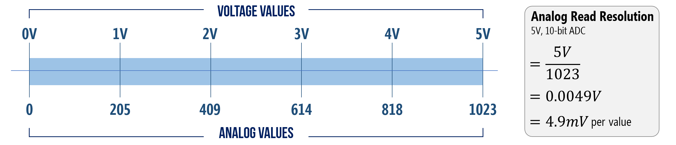 Figure. The Arduino Uno and Leonardo have 10-bit ADC’s, which convert analog voltages between 0 - 5V to an integer range of 0 - 1023. Thus, the ADC resolution is 4.9 mV (0.0049V).
Many newer Arduino boards use more modern 3.3V microcontrollers with higher-resolution ADCs. For example, The Arduino Nano 33 IoT and the ESP32 boards are both 3.3V with 12-bit ADCs.
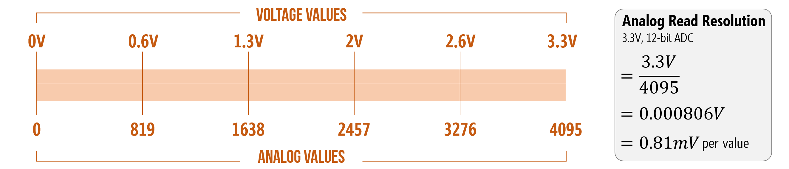 Figure. The Arduino Nano 33 IoT, Arduino Zero, and the ESP32 all operate at 3.3V with 12-bit ADCs (0 - 4095). Thus, the ADC resolution is 0.81mV.
Why does the ADC resolution matter?
For many purposes, it probably doesn’t. But the practical implication is that with a 5V board and a 10-bit ADC (like the Uno and Leonardo), we have a 0.0049V resolution. So, you won’t be able to tell the difference between, for example, 2.0070V and 2.0110V (both of which would convert to 411) or 4.8980V and 4.9010V (both of which would be read as 1003). Does this matter? It depends on the context—for most things we do, it won’t.
We discuss quantization in more depth in the Sensors and Signals sections.
Changing the HIGH reference voltage
The following two sub-sections on changing the reference voltage and how the ADC works internally are optional. You can skip ahead to Hooking up variable resistors with microcontrollers.
If you want to improve the ADC resolution, you have two choices: (1) up the bitrate, which would require different hardware (you can use an external ADC like this 12-bit ADS1015) or (2) decrease the convertible voltage range (so, applying the same 10-bits across a smaller voltage range).
It’s possible to do the latter on the Arduino. You can change the HIGH reference voltage from \(V_{cc}\) (which is 5V on the Uno and Leonardo) to a different value—for example, to 2V (1.0V is the minimum) using analogReference(). The LOW reference voltage is fixed to \(GND\).
Changing the reference voltage may be useful if you know your max analog input value is less than \(V_{cc}\) because you will increase your ADC precision.
On the Uno and Leonardo, the options are:
- DEFAULT: the default analog reference of 5V (on 5V boards) or 3.3V (on 3.3V boards)
- INTERNAL: a built-in reference equal to 1.1V on the ATmega328 (Arduino Uno). Note: The Arduino Leonardo (ATmega32u4) does not support
INTERNAL; instead, it hasINTERNAL2V56for a 2.56V reference. - EXTERNAL: the voltage applied to the AREF pin (between 1.0V-5V)
How does the ADC actually work?
But wait, you might wonder, how does the actual conversion from analog-to-digital work? This question is beyond the scope of our class; however, from our research, we found that the ATmega328 uses a successive approximation ADC, which converts continuous analog signals via a binary search through all possible quantization levels before converging on a digital output for each conversion (Wikipedia).
According to the ATmega328 datasheet, “the successive approximation circuitry requires an input clock frequency between 50 kHz and 200kHz to get maximum resolution. If a lower resolution than 10 bits is needed, the input clock frequency to the ADC can be higher than 200 kHz to get a higher sample rate.” See this EE StackExchange discussion.
Hooking up variable resistors with microcontrollers
Just like with our button lesson, let’s walk through how one might try to hook up a potentiometer with a microcontroller. As before, we’ll learn about what not to do and why as well as what to do.
Simple program to read analog input
Let’s first introduce a simple program to read and print analog input values to Serial. This will provide a convenient way to test our input circuits.
void setup()
{
  Serial.begin(9600); // for printing values to console
}

void loop()
{
  int potVal = analogRead(A0); // returns 0 - 1023 (due to 10 bit ADC)
  Serial.println(potVal);      // print value to Serial
  delay(50);                   // Reading new values at ~20Hz
}
Building an initial circuit
Let’s build an initial circuit in Tinkercad—first, the wrong way. And then we’ll fix it and show how to do it the right way.
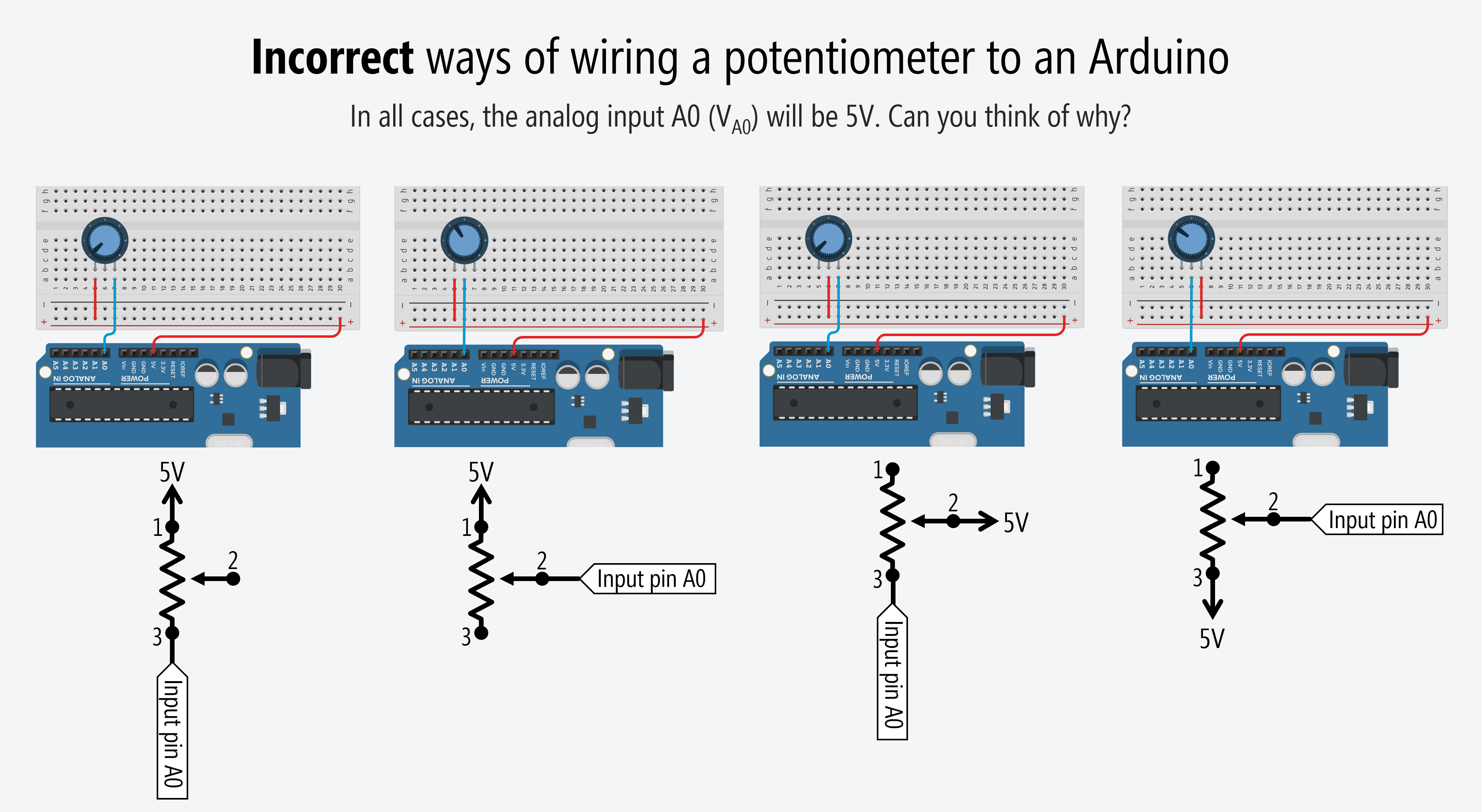
Incorrect potentiometer-based analog input circuit
To begin, you might treat the potentiometer similar to how we did with our LED circuits above—as a rheostat where we only use two legs (an outer leg and Leg 2). However, this won’t work. Build and try these configurations yourself. Make sure to add the above code to the “Code” window in Tinkercad and then hit the “Simulation” button.
 To try these incorrect circuits on Tinkercad, go here and here.
Why don’t these work?
Because, remember, our input pins measure voltage and there is no voltage difference across our potentiometer (because no current is flowing!). Here’s an illustrative video of what’s happening (and not happening) in our circuit:
This is a circuit simulation of Leg 1 of the potentiometer hooked to 5V and Leg 2 (wiper leg) hooked to A0. The “inside the microcontroller” view is for illustrative purposes. The input pin circuitry does not actually look like this. Simulation made in CircuitJS.
Notice how the analog input voltage \(V_{A0}\) to the microcontroller is always 5V? And, indeed, if you play with the Tinkercad circuits above, you’ll note that the Serial console simply prints 1023 continuously (which translates to 5V).
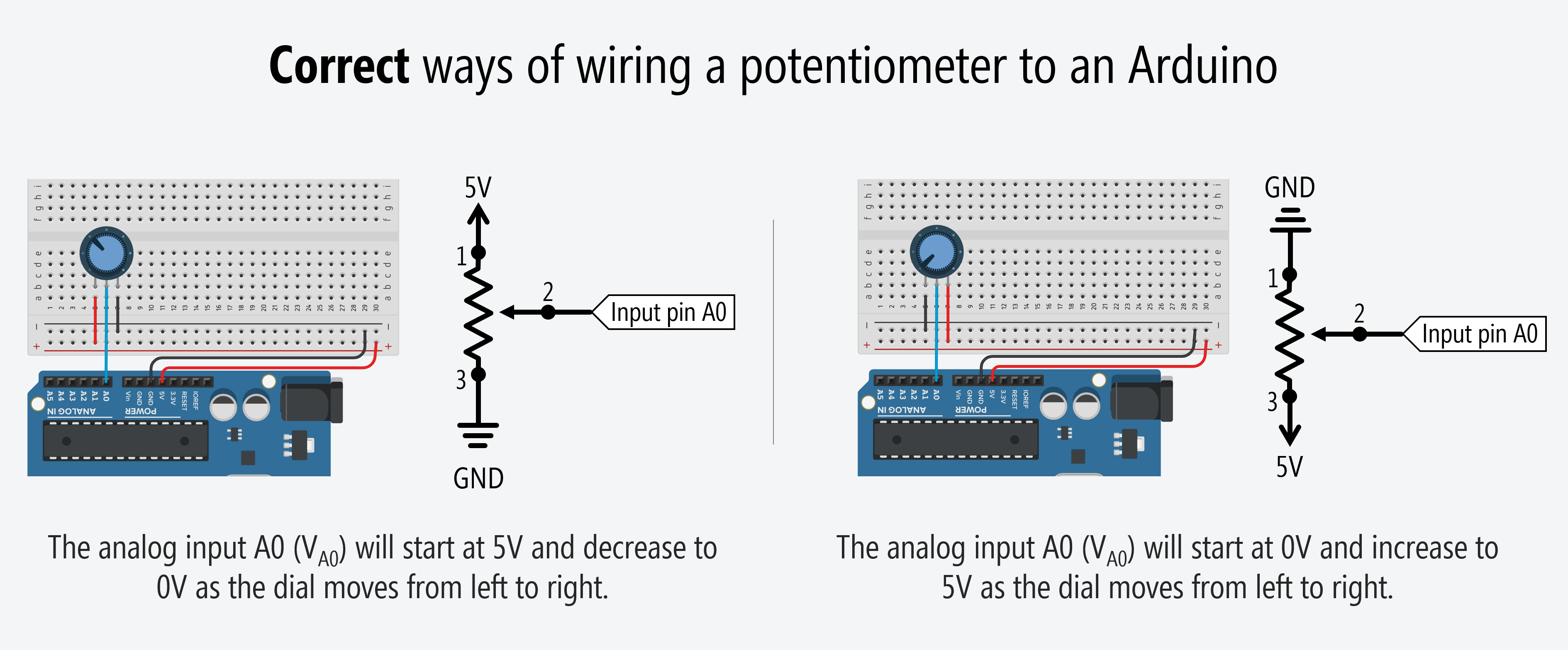
Correct potentiometer-based analog input circuit: voltage divider
So, what do we do? We hook up all three potentiometer legs to form a voltage divider: Leg 1 to \(V_{CC}\) and Leg 2 to \(A0\) but we’ll also wire Leg 3 to \(GND\). This will create a voltage difference across the potentiometer and cause current to flow from \(V_{CC}\) to \(GND\) (and a voltage divider network to emerge):
 Try this circuit+code out on Tinkercad.
Now \(V_{A0}=V_{CC} \cdot \frac{R_2}{R_1 + R_2}\).
And here’s an illustrative video of what’s happening in our circuit:
This is a circuit simulation of the potentiometer correctly hooked up to a microcontroller with Leg 1 hooked to 5V, Leg 2 (wiper leg) hooked to analog input A0, and Leg 3 to GND. The “inside the microcontroller” view is for illustrative purposes. The input pin circuitry does not actually look like this. Simulation made in CircuitJS.
Build it for real
Once you get the potentiometer-based analog input working in Tinkercad, build the physical circuit and, to begin, copy the code from above.
Exercises
Exercise 1: Potentiometer-controlled LED brightness
Read the analog input from your potentiometer using analogRead and use the value to set the brightness of an LED using analogWrite. Remember that analogRead returns 0–1023 while analogWrite accepts 0–255, so you’ll need to convert between the two ranges. (Hint: try integer division by 4, or use the map() function — we’ll cover map() in detail in the next lesson).
Exercise 2: Potentiometer-controlled tone
Hook up a piezo buzzer and use the potentiometer to control the pitch. Map the analogRead value (0–1023) to a frequency range like 100–2000Hz using map(). This combines your tone() skills with your new analog input skills!
Exercise 3: Slide potentiometer
If your kit includes a slide potentiometer, try using it in place of the trimpot. Does anything change in the code? Why or why not?
Exercise 4: Voltage display
Modify the simple analogRead program to convert the raw ADC value (0–1023) back into a voltage and print it to Serial. The formula in C++ would be: float voltage = analogReadValue * (5.0 / 1023.0);. Verify your results with a multimeter if you have one. This is essentially building a simple voltmeter!
Lesson summary
This lesson introduced analog input — one of the most important concepts in physical computing. Key takeaways:
- A potentiometer is a three-terminal variable resistor. The two outer legs have fixed total resistance; the middle leg (wiper) splits this into two variable resistances that always sum to the total.
- Potentiometers can be used as two-leg variable resistors (rheostats) for simple circuits like LED dimmers, or as three-leg voltage dividers for microcontroller input.
- Analog input lets the Arduino read voltages between 0V and 5V, not just
HIGHandLOW. The 10-bit ADC on the Uno and Leonardo converts these voltages to integer values from 0 to 1023. - Microcontrollers read voltage, not current. This is why a two-leg variable resistor alone doesn’t work as analog input — you need a voltage divider configuration (all three legs connected) so the microcontroller can “see” changing voltages.
- Use
analogRead(pin)to read analog input. The analog input pins (A0–A5 on the Uno) are separate from the PWM “analog output” pins. - Always prototype in Tinkercad first — it’s a great way to verify your circuit before building it physically.
Next Lesson
In the next lesson, we’ll learn how to use two-leg variable resistors like force-sensitive resistors and photocells with microcontrollers. Since these components only have two legs (unlike a potentiometer’s three), we’ll need to add a fixed resistor to create a voltage divider — a technique that unlocks a whole world of analog sensors!