Lesson 5: Using Resistors
Table of Contents
- How do resistors work?
- Resistors slow current everywhere
- How are resistors made?
- Characterizing resistors
- Reading resistors
- Activity
- Resources
- Next Lesson
Resistors are one of the most common and important electrical components in digital circuits. A resistor is a specially formulated component that resists the flow of charge (current) in a circuit. Just as we can reduce the flow of water in a pipe by inserting a valve packed with sand, clay, hair (bleah), or other permeable blockages, so too can we reduce the flow of electrons by inserting a component that has less conductive material than a normal wire.
In previous lessons, you learned about the concept of resistance, Ohm’s Law—how voltage, current, and resistance relate together—as well as series and parallel resistor configurations. In this lesson, we will expand on how resistors work, how they’re characterized in terms of both resistance \(R\) and power \(P\), and how to “read” them.
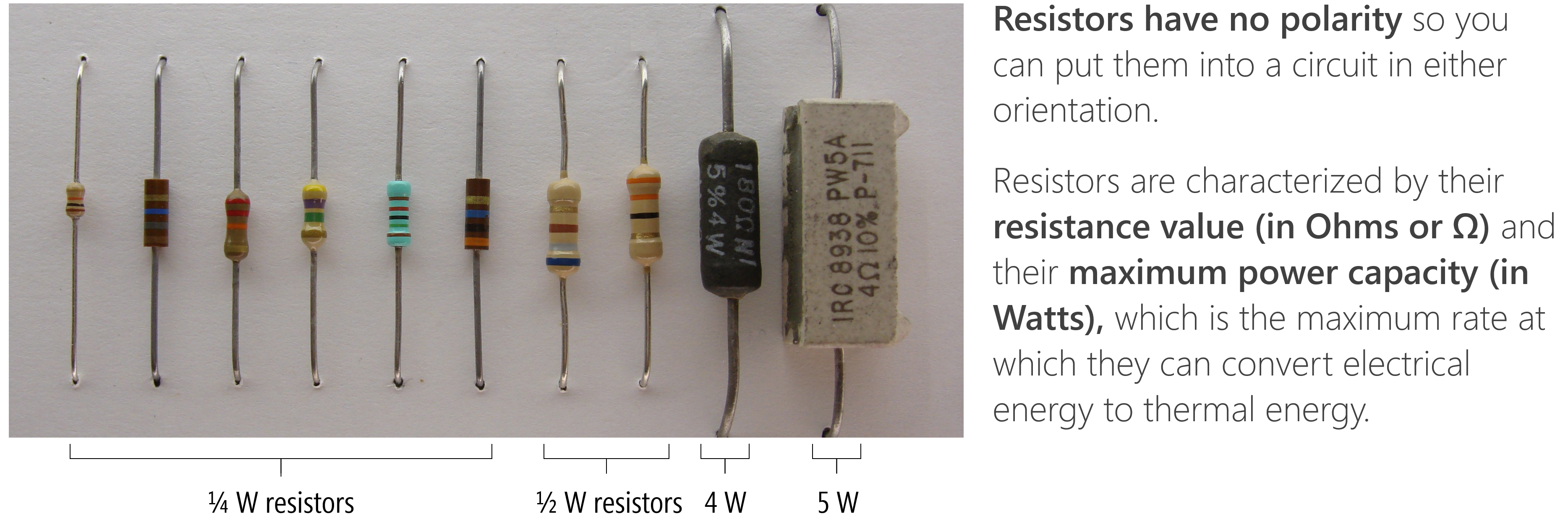
Figure. The above image shows a variety of resistor types from \(\frac{1}{4}W\) to \(5W\) resistors. I no longer have the source for the original image. Annotations made by Jon Froehlich in PowerPoint.
How do resistors work?
 Figure. This animation shows how a resistor can be placed between two wires to reduce current flow. Notice how electrons flow freely through the copper wire. With the resistor, these electrons “collide” with other atoms and themselves, which transforms the electrical energy to thermal energy and induces a voltage drop. Animation from The Engineering Mindset.
In a resistor, flowing electrons collide with atoms making them vibrate, which converts electrical energy to heat energy and induces a voltage drop \(V\). The amount by which a resistor resists the flow of charge is called its resistance \(R\) and is measured in Ohms (Ω). The amount of voltage drop over a resistor is captured by Ohm’s Law: \(V = I * R\).
Factors determining resistivity
As noted in Lesson 1, some materials like metals—silver, copper, and gold—have low resistances. Other materials such as glass, rubber, and air have high resistance and poor conductivity (“low electron mobility”)—these materials are called insulators.
But why?
There are three main factors that determine conductivity (see UIUC ECE110 notes):
- The ease with which electrons can be dislodged by an applied electric field. Metals like copper have easily displaceable electrons in their atom’s valence (outer) shells. It takes very little energy to cause electrons to “jump” or “move.”
- The atomic arrangement of the material. If you were able to look microscopically at metal, you would see a particular structural arrangement of atoms called a lattice—this structure depends on the material. For metals, atoms are densely packed, which lets electrons move relatively freely through the lattice, again reducing resistance.
- The temperature of the material. As a material heats up, its atoms vibrate with greater amplitude. This atomic motion has a negative effect on the material’s ability to conduct electric current, causing greater electrical resistance (link). Interestingly, the opposite is true for semiconductors—their resistance decreases with temperature, which is the operating principle behind thermistors that you’ll encounter later.
Resistors slow current everywhere
A common confusion is that resistors only reduce current at the resistors themselves or that resistors are like a traffic jam, slowing “traffic” (electrons) before the resistor but then the electrons (cars) “can pick up the pace” again after getting through the jam (the resistor). No, this is not correct!
Resistors restrict the flow of electrons throughout a circuit path. Think of a small valve in a water pipe: this valve restricts the total water flow through the pipe—both before and after the valve. The animation below shows three simple circuits with different amounts of resistance: notice how the current flow is the same throughout each circuit—it is not faster or slower before or after a resistor.
Video. In the animation above, we are showing how current is the same for each individual circuit. It does not speed up before or after a resistor. Animations made in CircuitJS (left, middle, right)
How are resistors made?
To make a resistor with a specific resistance \(R\), component manufacturers carefully select the type, amount, and shape of a resistive material and embed it into insulated packaging. In the image below, for example, a resistive material (like carbon) is wrapped around an insulator and covered by a tan insulating material. The more wraps, the higher resistance. And this should intuitively make sense: increasing the number of wraps simply increases the length of the resistive material (or the amount of resistive material electrons have to navigate through).
 Figure. Image from Sparkfun.com with annotations by Jon Froehlich.
Other resistors look like this inside:
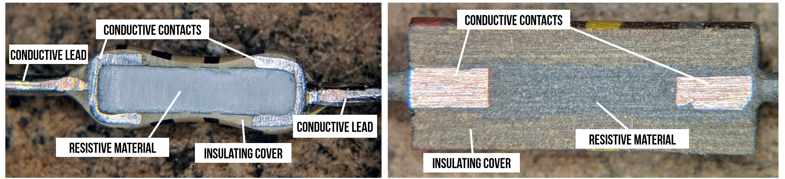 Figure. Two cross sections of non-wrapping resistors. Image from TubeTimeUS on Twitter with adapted annotations by Jon Froehlich. Right-click and “Open image in new tab” to expand.
Depending on their type and manufacturing, resistors have a certain “accuracy” tolerance. For example, a 100Ω resistor with a ±5% tolerance could be, in actuality, a 95Ω or 105Ω resistor.
Characterizing resistors
Resistors are characterized according to their resistance value (in Ohms or Ω) and maximum power capacity (in Watts), which is the maximum rate at which they can convert electrical energy to thermal energy (heat). We’ve previously described resistance, but what do we mean by power capacity?
What is electrical power?
Electric power—just like mechanical power—is the rate of doing work. The power \(P\) at a circuit element is a measure of how quickly it converts energy: a battery converts chemical potential energy to electrical energy (producing power), a resistor converts electrical energy to heat energy (absorbing power). Due to the conservation of energy, the total power delivered in a circuit is equal to the total power absorbed. The SI unit of power is the watt, one joule per second (\(\frac{J}{s}\)).
The amount of power \(P\) absorbed at a circuit element is dependent on both voltage and current:
\[P = V * I\]These UIUC ECE110 notes provide a nice explanation:
Voltage drop is the amount of electrical energy absorbed per +1 C of charge as it moves from the + label to the − label. Current is the amount of positive charge that flows per second in the direction of the arrow label. Multiplying these two quantities cancels out charge, and produces the amount of electrical energy absorbed per second, which is power.
That is, we know that \(P = V * I\). Adding in units, we get \(P = 1 V * 1 A\). From here, we can determine joules/second, which is the definition of power.
\[P = (1V)(1A) \Rightarrow (1 \frac{J}{C})(1\frac{C}{s}) \Rightarrow 1 \frac{J}{s} \Rightarrow 1 W\]Thus, electric power is the amount of charge \(Q\) coulombs passing through an electric potential (voltage) difference \(V\) over time \(t\).
But the most critical thing to understand and remember is \(P=V * I\)!
Calculating the power dissipation of a resistor
While \(P\) is defined as \(P=V * I\), we can use Ohm’s Law and simple substitution to derive two other formulations:
\[P = V*I = I^2 * R =\frac{V^2}{R}\]For example, consider a circuit with a 9V battery and a 100Ω resistor, how much power does the resistor absorb? \(P = \frac{V^2}{R} \Rightarrow \frac{9^2V}{100Ω} = 0.81W\). In our prototyping kits, we typically supply \(\frac{1}{4}W\) resistors, which are 3.2x too small to dissipate 0.81W of power.
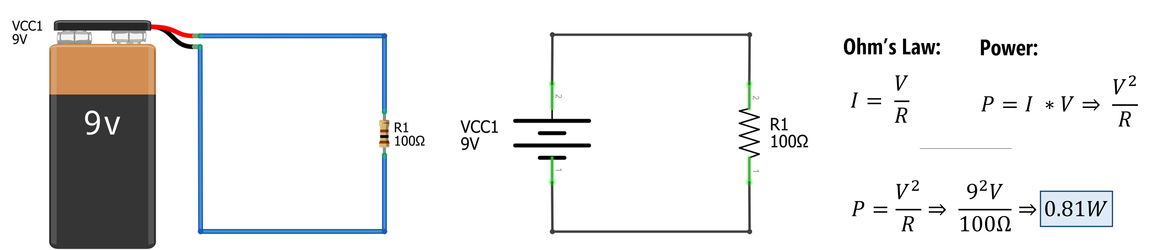
Figure. Calculating the power dissipation of the resistor \(R_1=100Ω\) in a circuit with a 9V battery. Using Ohm’s Law to replace the \(I\) with \(\frac{V}{R}\) in \(P=I * V\), we can solve for \(P\) with \(\frac{V^2}{R} \Rightarrow \frac{9^2V}{100Ω} = 0.81W\)
To meet the minimum power ratings of our \(\frac{1}{4}W\) resistors, we would need to replace the 100Ω resistor with a ~330Ω resistor. To determine this, we can simply solve for \(R\) with \(P=\frac{1}{4}W\). That is, \(P = \frac{V^2}{R} \Rightarrow 0.25W = \frac{9^2V}{R}\). Solving for \(R\), we get: \(R = \frac{9^2 V}{0.25W} = 324Ω\).
Engineering Rule of Thumb: Power Derating. While our math shows exactly how much power a resistor will absorb, running a component at or near its maximum rating in the real world causes it to get very hot and drastically shortens its lifespan!
To account for this, engineers apply a derating factor—usually 50%. This means you should select a resistor with a power rating at least double what your circuit calculates. So, if your math says you need to dissipate 0.125W, a 0.25W resistor is perfect. If you need to dissipate 0.2W, you should step up to a 0.5W resistor for a reliable, cool-running circuit.
What if the maximum power capacity is exceeded?
If we exceed a resistor’s power capacity, it will begin to heat up and eventually burn out. Once a resistor “burns out”, it typically creates an “open circuit”—that is, current will no longer travel through that path (air is a good insulator).
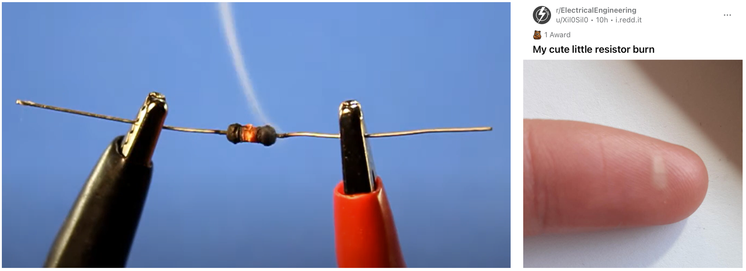 Figure. Resistors are made of materials that cause electron collisions with atoms, generating heat. Resistors have “power ratings” that, when exceeded, can heat up too much and burn out (left image). If you overpower your resistor, it could burn you—be careful. On the right image, a Reddit user posted their resistor burn imprint on their finger. Image on left from this Being Engineers video and image on the right from the Electrical Engineering sub-reddit by user Xil0Sil0 (link).
Notably, I’ve never had a resistor start on fire or burn up (though I have had them heat up to the point in which they are “hot to the touch”). If you smell something burning, immediately unplug your power supply.
Identifying a burnt resistor. A burnt-out resistor often shows visible signs: darkened or charred body, a burnt smell, or discoloration of the circuit board underneath. If you suspect a resistor has failed, measure it with a multimeter—a burnt resistor will typically show an extremely high or infinite resistance reading (because the internal connection is broken, creating an open circuit).
Reading resistors
There are three ways to determine a resistor’s value: (1) keep them organized in pre-labeled packs (sidestepping the problem entirely); (2) decode the color-coded bands printed on the resistor body; or (3) measure the resistance directly using a multimeter—this is the most reliable method and works regardless of color band condition or visibility.
Resistor kits
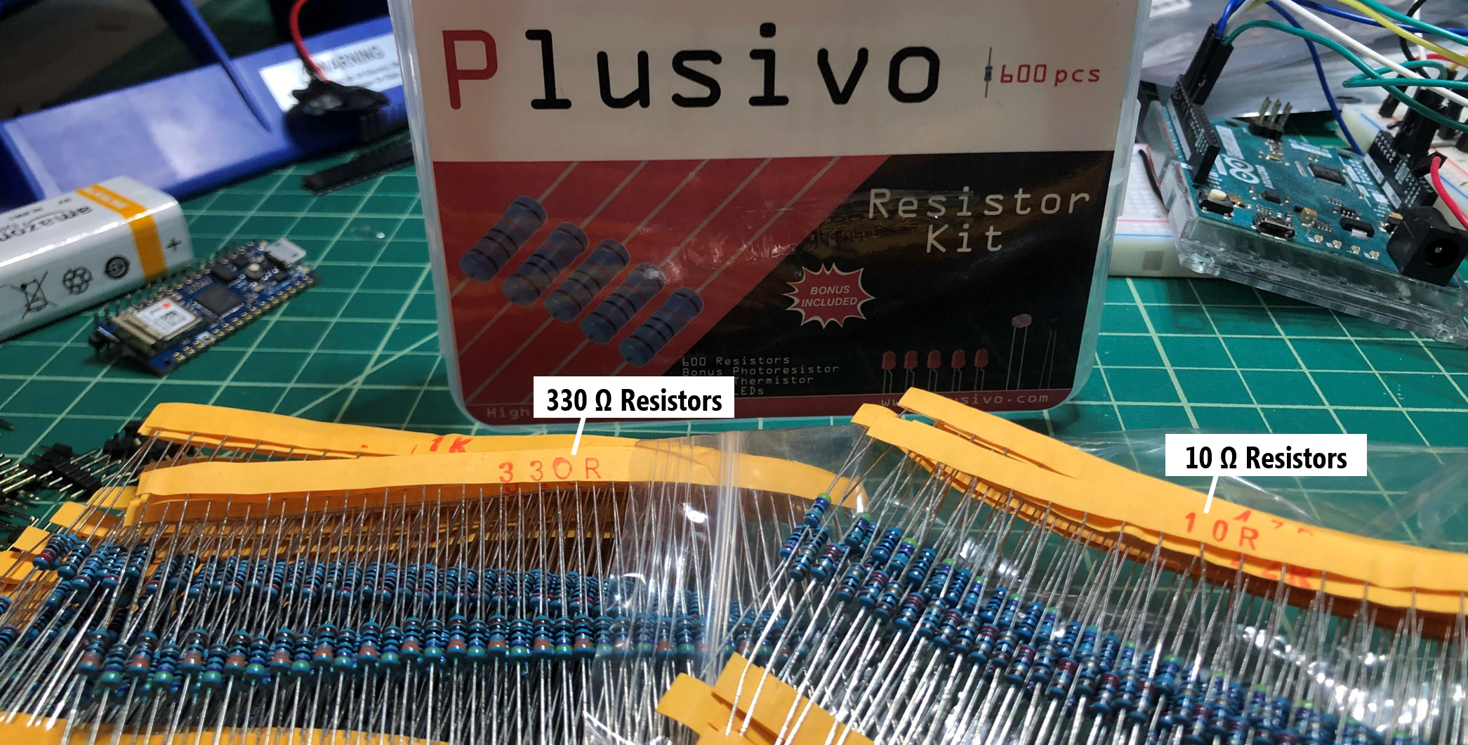
In our prototyping classes, we tend to purchase \(\frac{1}{4}W\) resistor kits, which come with a set of resistors organized by resistance value and labeled (though you pay more per resistor for the convenience).
 Figure. The Sparkfun resistor kit comes with 500 \(\frac{1}{4}W\) resistors with ±5% tolerance (and costs ~$7.55 in bulk, which is $0.015/resistor) while the Plusivo resistor kit comes with 600 \(\frac{1}{4}W\) resistors with ±1% tolerance (currently $8.99 on Amazon, which is $0.015/resistor).
Reading resistor color bands
If you don’t have your resistors pre-labeled in a pack, you’ll need a method to determine their resistance value. Unfortunately, unlike capacitors, resistors do not have textual labels printed on them. Instead, they use a color coding system that has long been standardized but is a bit arcane (and not particularly accessible to people with color vision deficiency).
But knowing how to read these color bands is a nice skill for any prototyper, even if you do not memorize the color legend (I tend to look back at a reference, even now!).
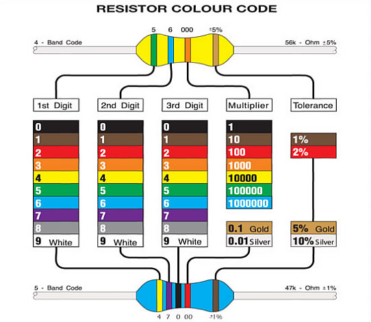
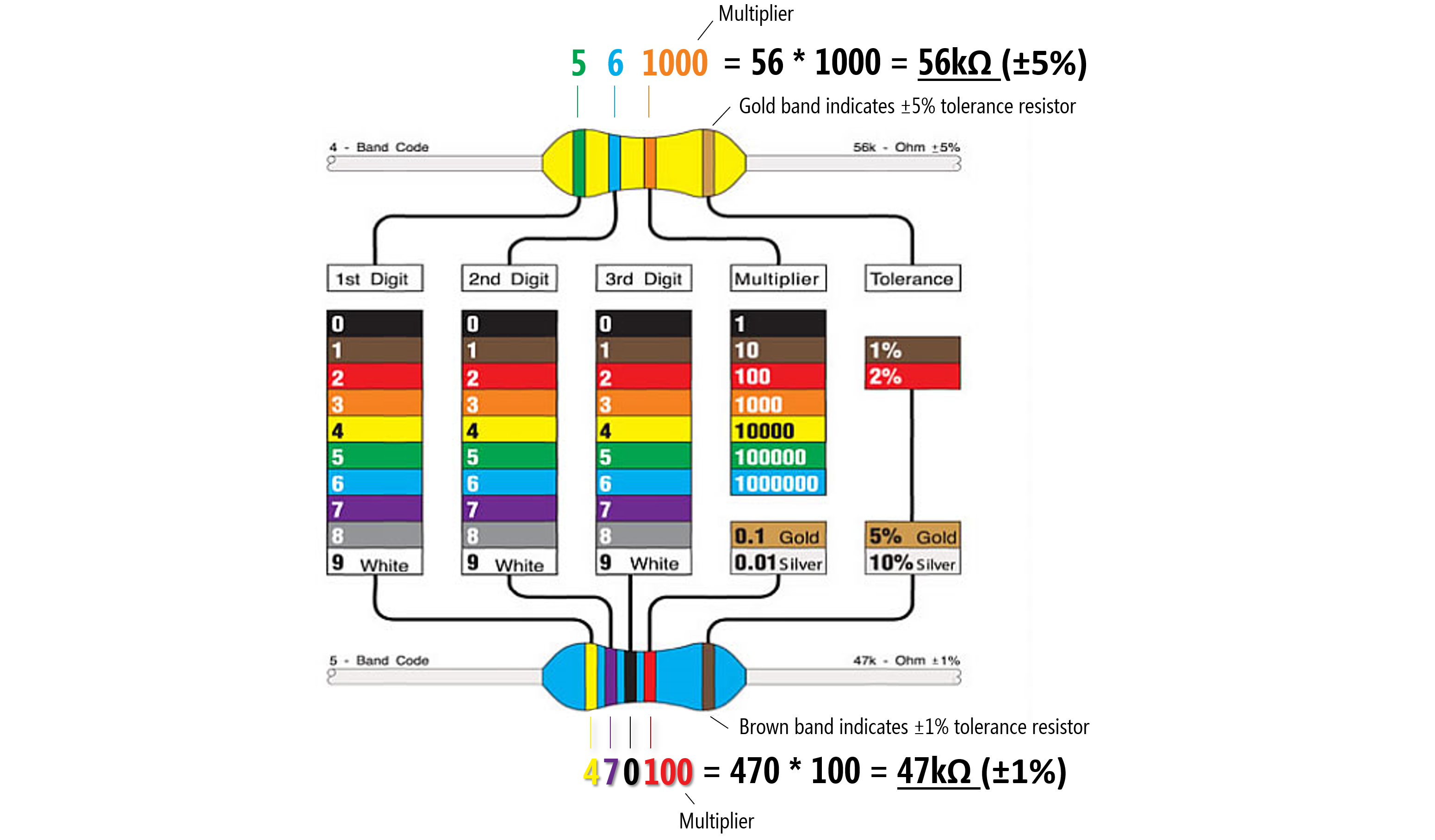 Figure. A legend for the color bands used on resistors and two examples: on the top, a tan ±5% tolerance resistor with green (5) and blue (6) digits and an orange multiplier (1000) color bands, which is \(56 * 1000 = 56kΩ\). On the bottom, a blue ±1% tolerance resistor with yellow (4), purple (7), black (0) digits and a multiplier of red (100), which is \(470 * 100 = 47kΩ\). Image modified from here.
To read the resistor color bands, orient the resistor such that the “tolerance” band (e.g., the gold band for tan resistors or a brown band for blue resistors) is on the right. Then you read the color bands left-to-right based on the color chart below. Notably, the color band just before the tolerance band is a multiplier and the preceding bands are digit bands that tell you what to multiply.
So, if you have a four band resistor that ends in a gold stripe (±5% tolerance) and has the colors red, red, brown. Then those colors correspond to 2, 2, and a multiplier of 10, which would be \(22 * 10 = 220Ω\). If you have a 4.7kΩ resistor, you would have colors yellow (4), purple (7), and a multiplier of red (100) so that \(47 * 100 = 4700 \Rightarrow 4.7kΩ\).
Confused? That’s ok!
In the video below, I slowly walk through how to decode the color bands on resistors with some examples. Then I show how to use a multimeter to read the resistance values directly. Hopefully, this will make things clearer.
Video. A video tutorial of how to decode the resistor color codes and how to “read” a resistor’s value using a multimeter.
Accessibility alternatives to color bands. If you have difficulty distinguishing resistor color bands, there are several alternatives. Smartphone apps like Electrodoc or Resistor Scanner can use your phone’s camera to identify resistor values. A multimeter remains the most reliable method regardless of visual ability. Additionally, surface-mount (SMD) resistors—commonly found on printed circuit boards—use numerical codes rather than colors (e.g., “472” means 4700Ω or 4.7kΩ).
Activity
For your learning activity, pick out three different resistors from your kits. In your prototyping journals, for each selected resistor, take a picture, write down the color bands, and then manually calculate the resistance (showing your work). In the Plusivo kits, the resistors come in labeled strips, which you can use to check your work (ground truth!) or, if you have access to a multimeter, you could do that too. If you do use a multimeter, do you notice any differences between the color-coded value and the measured resistance in practice? Why do you think this might be?
Resources
-
Experiment 3: Your First Circuit, Platt, Make: Electronics, 2nd Edition
-
Chapter 10: Resistor in Platt, Make: Encyclopedia of Electronic Components Volume 1: Resistors, Capacitors, Inductors, Switches, Encoders, Relays, Transistors, O’Reilly, 2012.
-
Resistance and Ohm’s Law, UIUC ECE110
-
What is Resistance?, UIUC ECE110
-
Power, UIUC ECE110
Next Lesson
In the next lesson, we will learn about light-emitting diodes and how to use them.