Lesson 1: Turning on an LED
Table of Contents
- Materials
- Hook up LED to Arduino’s 5V supply pin
- Stepping down power supply voltages
- How can we make the LED less bright?
- Exercises
- Lesson Summary
- Next Lesson
For our first learning activity, we are going to use Arduino to turn on an LED. We’re not going to write any code. Instead, our goal is to build some initial familiarity with Arduino hardware and connecting components to Arduino pins before we introduce programming, which we do in the next lesson.
Figure. The movement of current in the circuit is illustrated by the animated yellow circles. This visualization is a coarse abstraction designed to emphasize the direction of current flow. A more accurate visualization would show that electrons are already distributed throughout a wire before a voltage is applied. See our Introduction to Electronics series, specifically the lesson on Voltage, Current, and Resistance.
Materials
For this lesson, you will need the following materials. Please build with us to advance your understanding and skillset—the best way to learn is by doing! For those students enrolled in our courses, please document your creation journeys in your prototyping journals and attempt to answer and reflect on posed questions.
| Arduino | LED | Resistor |
|---|---|---|
 |  |  |
| Arduino Uno, Leonardo, or similar | Red LED | 220Ω Resistor |
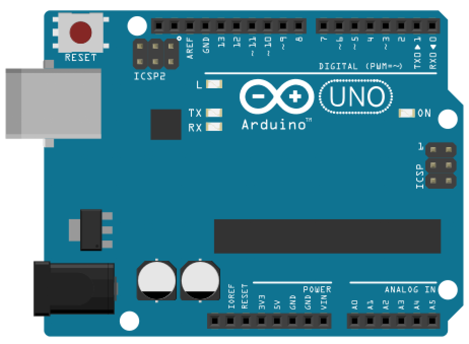
We’ll be using the Arduino Leonardo for these introductory microcontroller lessons but any 5V board will work, including the Arduino Uno, Adafruit’s METRO 328, Sparkfun’s RedBoard, etc. Each of these boards has the same pin layout and general specifications.
Hook up LED to Arduino’s 5V supply pin
Let’s begin by hooking up an LED with a current limiting resistor to the Arduino’s 5V supply pin.
Step 1: Wrap resistor around LED leg
Grab a 220Ω resistor (or any resistor 220Ω or greater) and twist one leg around an LED leg. If you want to follow my example exactly, connect the resistor to the LED’s anode (long leg) but either leg will work. (Remember, a current limiting resistor can go on either side of an LED, see our LED lesson).
To wire wrap your components, simply twist the legs together like this:
Figure. An example of wire wrapping a 220Ω resistor leg (or lead) directly around the anode of an LED.
Step 2: Connect components to Arduino
Insert the LED + resistor into the Arduino:
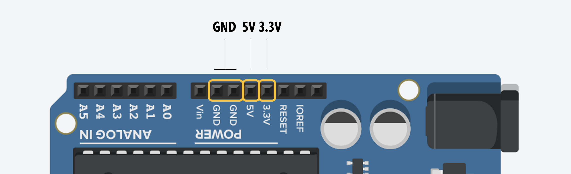
- Connect the LED’s cathode (short leg) to GND
- Connect the LED’s anode (long leg) + resistor to the Arduino’s voltage supply, which you can access via the 5V pin
Make sure to push the legs down so they are well seated inside the Arduino’s female headers.
Step 3: Connect your Arduino to power
Now connect your Arduino to power and the LED should light up. You did it!
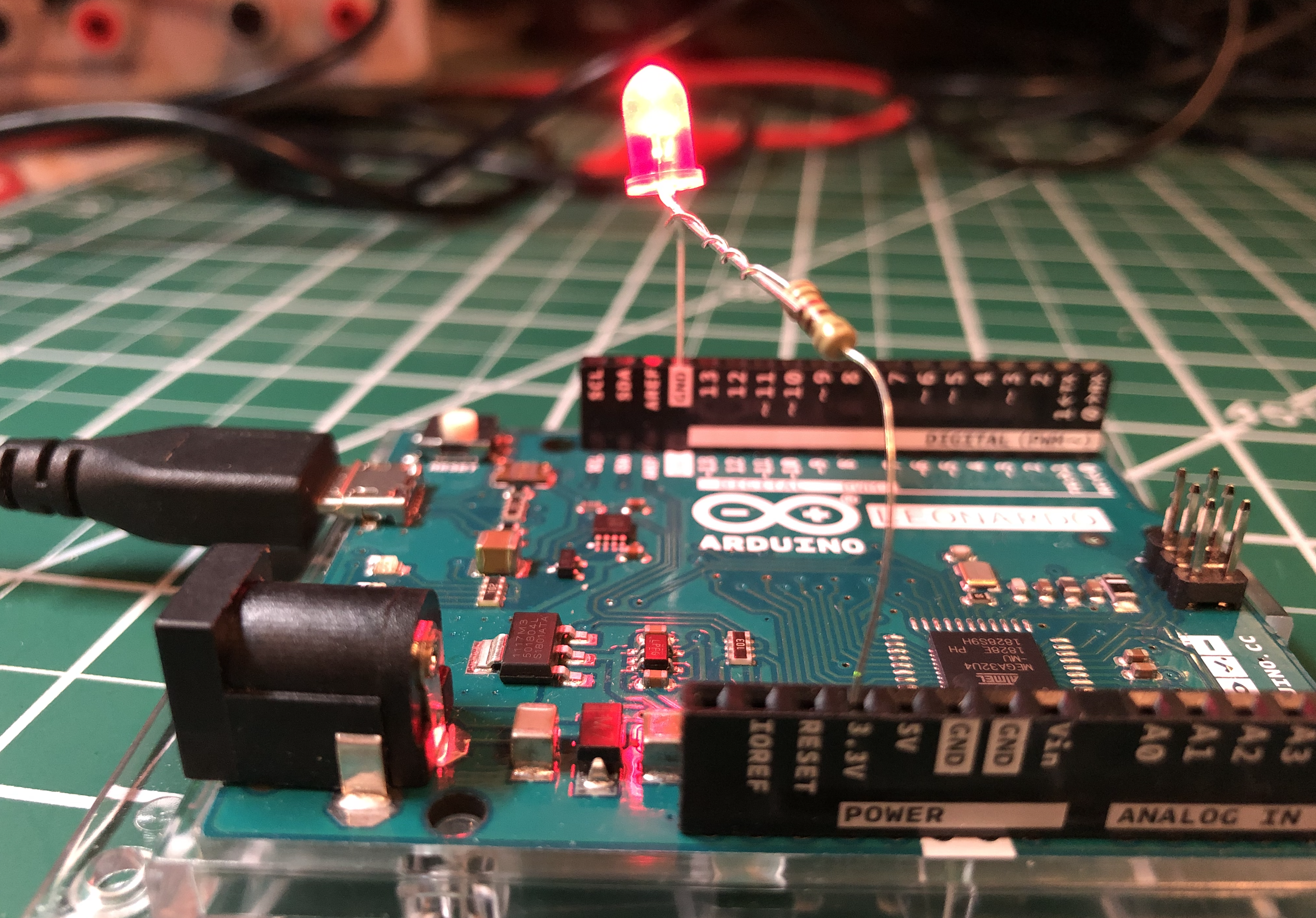
Here’s a photo of the version I made. I found it easier to stretch the wiring across the Arduino from the 5V port to the GND on the opposite side.
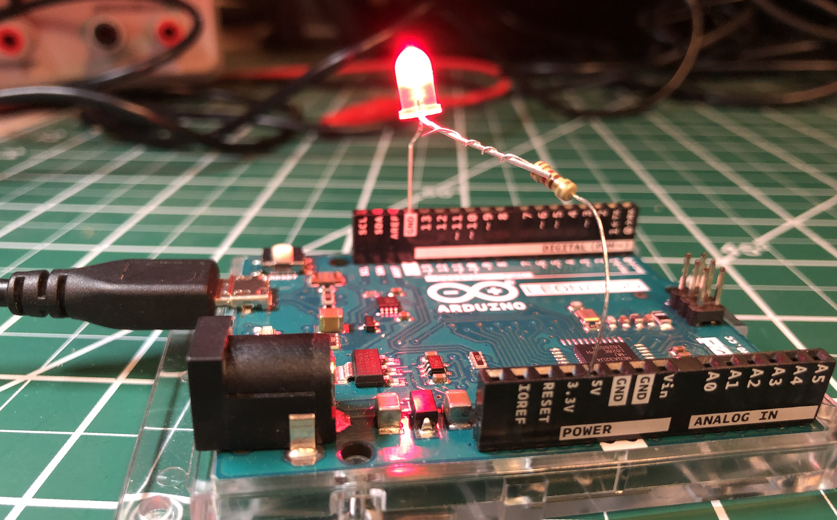
For power, you can use a USB cable (which supplies 5V) or a 9V battery (which supplies 9V). Either way, the Arduino supplies 5V through the 5V pin. How? Using a voltage regulator. See Stepping down power supply voltages below.
| USB Power | 9V Power |
|---|---|
| With USB power, the 5V pin supplies 5V | Using the Arduino’s barrel jack, we can connect an external power supply like a 7-12V wall adapter or a 9V battery. The Arduino’s internal voltage regulator reduces these higher voltages to output a clean 5V |
Leonardo Users: If you are using a 9V battery or external battery pack, double-check your polarity! Unlike the Uno, the Leonardo does not have series reverse-polarity protection on its power jack. Plugging a battery pack in backward can permanently damage the board. See Reverse Polarity Protection: Uno vs. Leonardo.
Let’s analyze our circuit
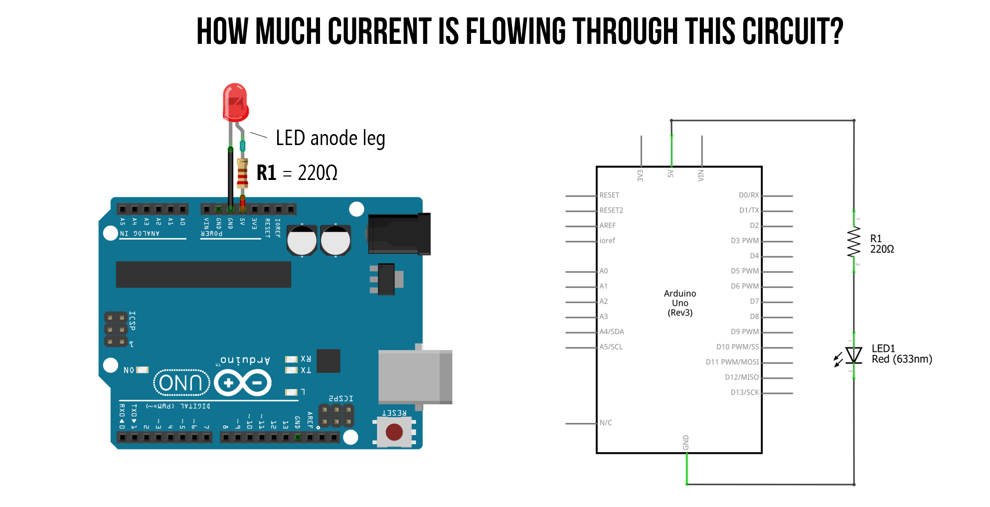
Just as we did in our LED lesson, let’s analyze how much current is flowing through this simple LED-based circuit. To do this, we first need to determine the voltage drop across the resistor \(V_R\) and then use Ohm’s Law to figure out the current (\(I = \frac{V_R}{R}\)).
While it’s not totally necessary to understand circuit basics to work with Arduino—indeed, you can get pretty far just by following online tutorials—we think it’s pretty important. As my colleague Professor Andy Davidson likes to say: there is a difference between a chef who understands how ingredients go together and creates their own dishes vs. a novice baker who simply follows recipes. We all start like the latter but we want to develop you more into the former! Let us all become chefs! 👩🏽🍳👨🏽🍳
So, while you could skip this section and go on to Maximum current draw below, we recommend that you instead invest in this circuit analysis and do your best to understand it. If you’re confused, try going through our Intro to Electronics series, particularly Ohm’s Law and LEDs.
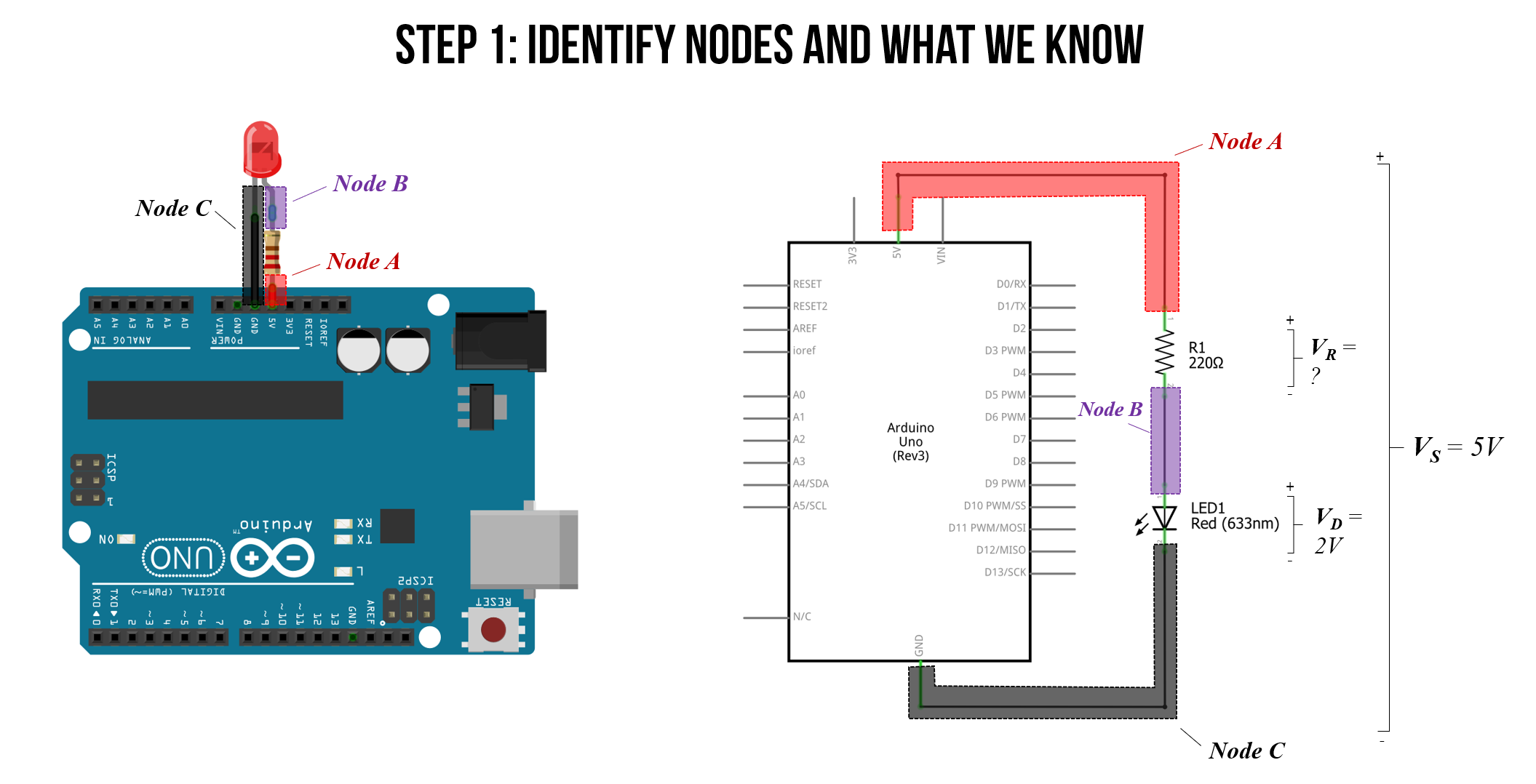
Step 1: Identify nodes and what we know
When analyzing a circuit, we always start by identifying nodes and what we know. We know that:
-
As long as the forward voltage (\(V_f\)) of the red LED is satisfied, then there will be both a voltage drop \(V_R\) across our resistor and a voltage drop \(V_D\) across our LED.
-
Due to Kirchhoff’s Circuit Laws, we know that the total voltage drop across both the resistor and LED (\(V_R + V_D\)) must equal our supply voltage \(V_S=5V\).
-
Finally, from our LED lesson, we know that our circuit is off until the “on” or “forward” voltage of our LED is met, which for a red LED is ~2V.
From the above, we can set \(V_D=2V\) and solve for \(V_R\).
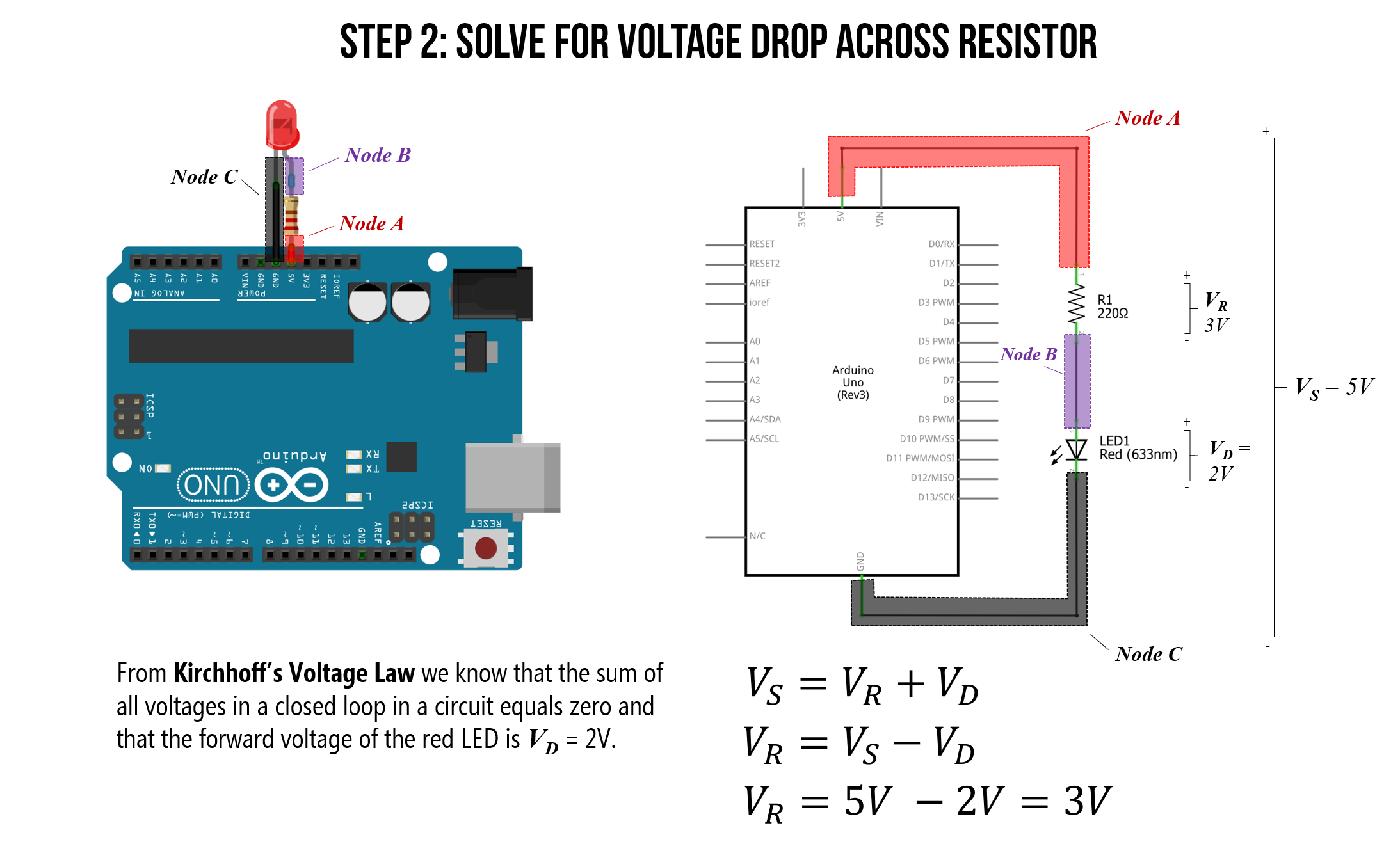
Step 2: Solve for voltage drop across the resistor
Using the RED LED’s forward voltage of \(V_D=2V\), we can now solve for the voltage drop across the resistor \(V_R\). This will enable us to then calculate the current.
\[V_S = V_R + V_D \\ V_R = V_S - V_D \\ V_R = 5V - 2V = 3V\]Thus, the voltage drop across the resistor is \(V_R=3V\). Let’s take a look pictorially below:
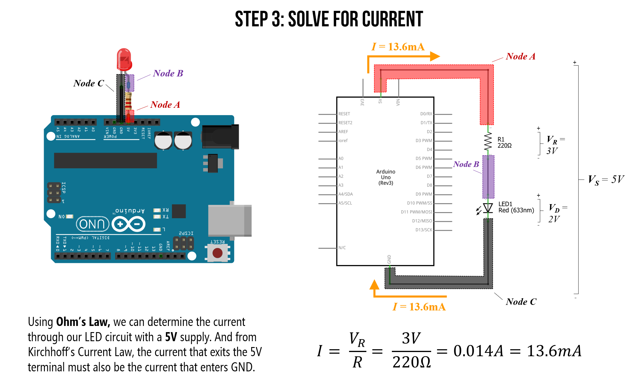
Step 3: Solve for current
We now know the voltage drop over the resistor in our circuit (\(V_R=3V\)), so we can solve for current.
From Ohm’s Law, we know that the total current in our circuit is equal to the voltage drop across our resistor \(V_R\) divided by the resistance value \(R\). That is, \(I = \frac{V_R}{R}\). And we know that \(V_R=3V\) and \(R=220Ω\). Thus, the current through our circuit is:
\[I = \frac{V_R}{R} \\ I = \frac{3V}{220Ω} = 0.014A = 13.6mA\]Let’s again take a look at this pictorially:
So, with the 5V supply pin, our simple LED-based circuit is drawing 13.6mA of current. Is this a lot or a little? Short answer: it’s not very much but let’s put this in context below.
Maximum current draw
The Arduino has a variety of pin types, each with their own maximum current ratings.
-
I/O Pins: The maximum current draw of any single I/O pin—which we haven’t used yet but we will in the next lesson—is 40 mA (a safer, continuous range is ~20mA). The total current across all I/O pins together is 200mA. If we exceed these values, we could damage our Arduino board or the underlying microcontroller (the ATmega328 for the Uno or the ATmega32u4 for the Leonardo).
-
Power supply pins: The 5V output pin can supply ~400-500mA when powered by USB and ~900-1000mA when using an external power adapter. The 3.3V output pin can supply ~150mA; however, if you have both 3.3V and 5V output pins connected, any current drawn from the 3.3V pin will be counted against 5V’s total current.
The only protection fuse is a resettable polyfuse on the USB port, which limits current to 500mA on the 5V output pin (but only when powered by USB).
There are a variety of discussions about the Arduino Uno and Leonardo’s maximum current draw online. The best resources I’ve found are these StackExchange posts, which also link to datasheets (post1, post2).
Maximum number of LEDs in series
An interesting question to ponder then is: with the Arduino powered via USB (max 500mA current), how many red LEDs could you hook up in series to the 5V supply pin? How about in parallel? What is the limiting factor for each?
Well, for a simple series configuration, the total number of series LEDs is limited to the voltage supply, which is 5V. With a 200Ω resistor and a red LED with a “forward” voltage of \(V_f=2V\), we are limited to a maximum of two LEDs: \(2 * 2V = 4V\). However, in practice, I was able to get three LEDs in series (because the LED begins to turn on a bit around ~1.7-1.8V) though they were quite dim. See the table and image below for my measurements.
| Resistor | Num Red LEDs in Series | Voltage Drop Across Each LED | Voltage Drop Across Resistor | Current |
|---|---|---|---|---|
| 200Ω | 1 | 2.02V | 2.95V | 14.9mA |
| 200Ω | 2 | 1.92V | 1.21V | 6.1mA |
| 200Ω | 3 | 1.71V | 0.021V | 0.1mA |
| 200Ω | 4 | 1.01V | ~0V | ~0 mA |
Table. For this empirical measurement test, I used the Sparkfun 5mm diffused RED LEDs.
Here’s a picture of the test setup and circuits for the measurements above:
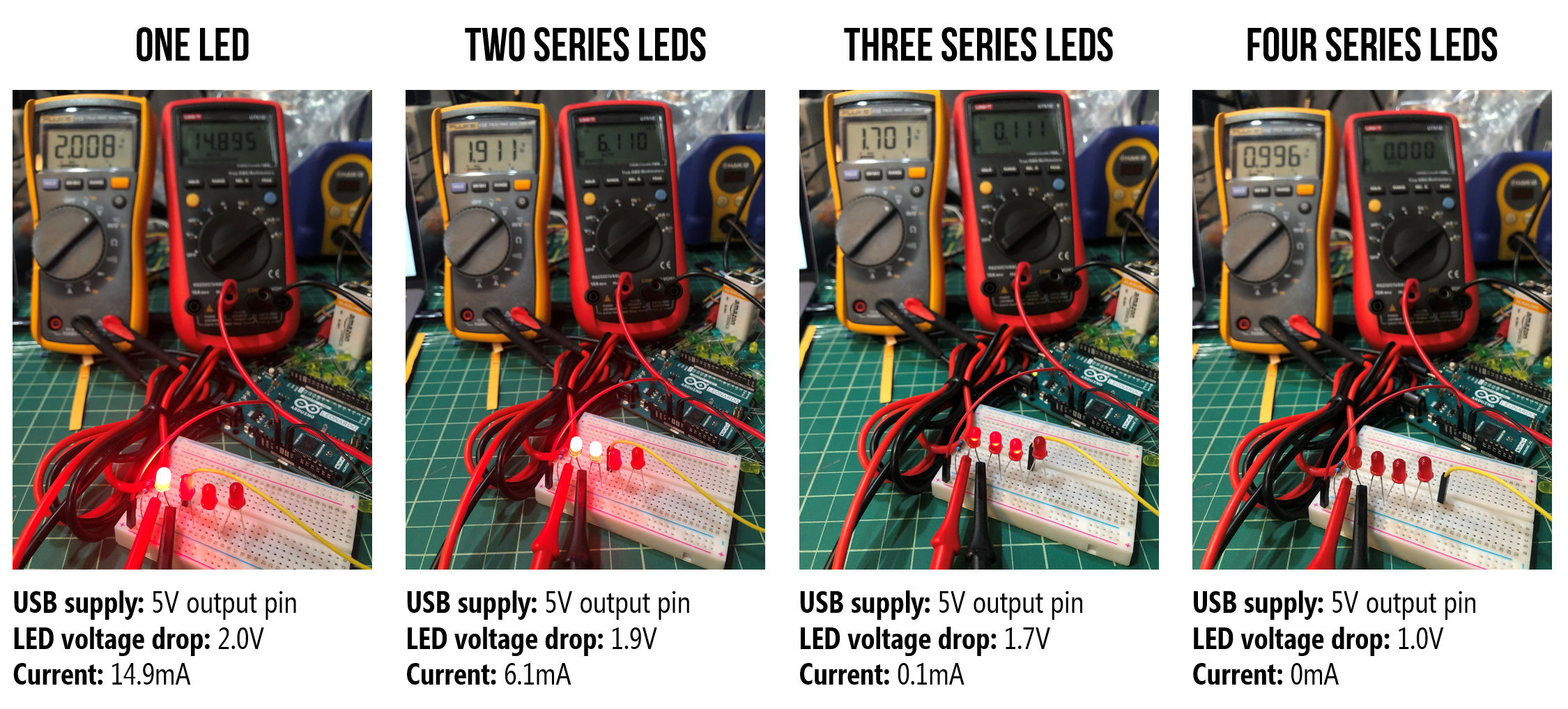 Figure. Measuring the individual LED voltage drop and current through the circuit using two multimeters: the yellow multimeter configured as a voltmeter to measure the voltage drop \(V_D\) over the first LED in the circuit and the red multimeter configured as an ammeter to measure the current \(I\) through the circuit.
Finally, we can also examine this circuit in a simulator, which mirrors our empirical measurements:
Figure. A CircuitJS simulation of various LED series configurations with a 5V voltage supply.
Maximum number of LEDs in parallel
For the parallel configuration, the limiting factor is the total amount of current we can source, which with the 5V pin powered by USB, is 500mA. How many red LEDs does it take to exceed 500mA using 200Ω resistors?
Well, in a parallel configuration, each resistor+LED branch is getting ~\(I=\frac{V_R}{R}=\frac{3V}{200}=15mA\). Thus, the maximum number of LEDs in parallel is \(\frac{500mA}{15mA}=33.3\), so at most 33 LEDs before exceeding the limit.
 Figure. 34 LEDs in parallel draw 514.1mA of current, which exceeds the 500mA maximum of the 5V output pin on the Arduino (when powered by USB). The safe maximum is 33 LEDs. Here’s the CircuitJS link.
I attempted to “stress” test the maximum values a bit using the USB port on an old MacBook Pro (do not do this!). Even though I exceeded both the 500mA limit with the 5V output pin (563mA) and the 150mA limit with the 3.3V pin (314mA), I did not trigger the fuse. However, I only kept the board plugged in for a short time.
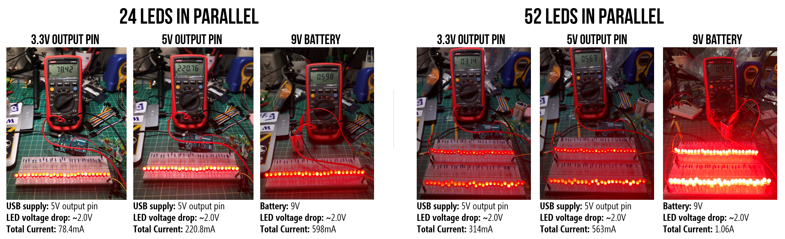 Figure. I “stress tested” the 5V output pin using the USB for power. Do not attempt! Despite exceeding the rated maximums, I failed to trigger the Arduino’s internal fuse on the 5V or 3.3V supplies. Note, the I/O pins do not have such protect so you could damage your board if you overdraw current.
Stepping down power supply voltages
If we plug in a 7-12V wall adapter or a 9V battery to the Arduino’s barrel jack, then how does the Arduino convert these higher voltages to 5V? Using a component called a voltage regulator, which can take in a range of DC voltages and step it down (but not up) to a stable constant voltage. The Arduino Uno uses a linear voltage regulator (the NCP1117), which dissipates the excess voltage as heat—this is why your Arduino can get warm when powered by a higher-voltage supply. You can buy and use voltage regulators in your own projects. If you want to learn more about the Arduino Uno’s power supply sub-system, read this technobyte blog post.
How can we make the LED less bright?
LED brightness is controlled by current. So, to dim an LED, we need to reduce current. But how? Recall Ohm’s Law: \(V=I * R\) or \(I = \frac{V}{R}\). Thus, we can reduce current either by:
- Decreasing voltage
- Increasing resistance
In future tutorials, we’ll show how you can control voltage output programmatically by writing code for the Arduino microcontroller. But, for now, let’s dim the LED by first decreasing voltage using the Arduino’s 3.3V pin (rather than the 5V pin) and then by using higher value resistors. This is similar to the activities in our LED lessons but now we are using the Arduino’s pins as a voltage source.
Hooking up the LED to the 3.3V supply pin
The Arduino Uno provides both a 5V power supply (which we just used) and a 3.3V power supply.
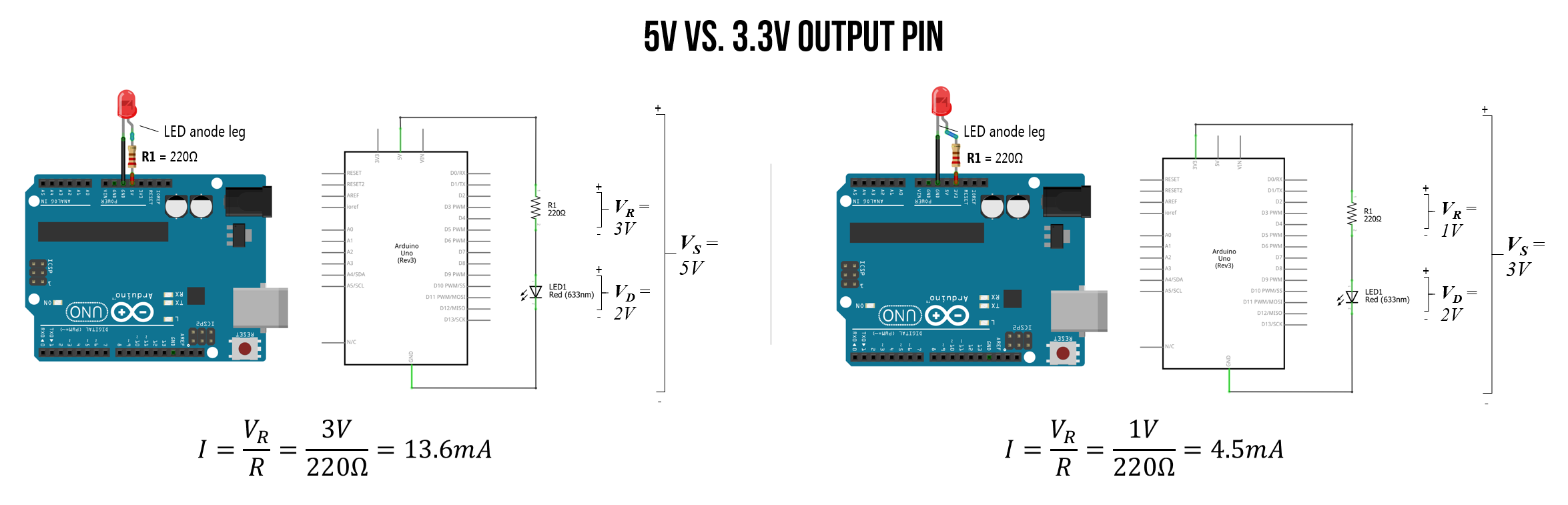
Let’s move the LED anode (long leg) from the 5V pin to the 3.3V pin but keep the 220Ω resistor. What do you observe? The LED should be less bright! This is because there is less current flowing through the 3.3V circuit.
Recall from above that with 5V, we have \(I=\frac{V_R}{R}=\frac{3V}{220Ω}=13.6mA\). With the 3.3V output pin, this drops to \(I=\frac{V_R}{R}=\frac{1.3V}{220Ω}=5.9mA\)
Here’s a workbench photo of the LED wired to the 3.3V port. The LED is noticeably less bright:
Full video walkthrough
Here’s a full video walkthrough of wrapping the resistor around the LED anode leg, wiring the circuit to 5V and GND, and then switching from the 5V to the 3.3V supply.
Using higher value resistors
We just showed how reducing the supply voltage (\(V_s\)) proportionally reduces current and, therefore, the LED brightness. Now, let’s play around with higher-value resistors such as a 680Ω, 2.2kΩ, or 10kΩ, and see their effect. What happens?
You should observe that the LED’s brightness decreases as the resistance increases because LED brightness depends on current (\(I = \frac{V_R}{R}\)).
| Resistor | Resistor Image | Vs | Resulting Current |
|---|---|---|---|
| 220Ω |  | 5V | \(I = \frac{3V}{220Ω}= 13.6mA\) |
| 680Ω |  | 5V | \(I = \frac{3V}{680Ω}= 4.4mA\) |
| 1kΩ |  | 5V | \(I = \frac{3V}{1,000Ω}= 3mA\) |
| 2.2kΩ |  | 5V | \(I = \frac{3V}{2,200Ω}= 1.4mA\) |
| 10kΩ |  | 5V | \(I = \frac{3V}{10,000Ω}= 0.3mA\) |
We can verify these theoretical predictions using a multimeter to measure (\(V_s\)), the actual resistor values, and the current \(I\). We conducted these measurements using a Fluke 115 True RMS Multimeter.
A few important notes:
- Each electronic component that we use—from the LED to the resistors to the supply voltage (\(V_s\))—is going to differ slightly from ideal. Our carbon film resistors, for example, have a tolerance of 5% (indicated by the gold band), and I measured our supply voltage on the Arduino Uno to be (\(V_s\)=4.902V) rather than 5V.
- The Fluke 115 provides three digits of precision. So, the multimeter reads 0.013A, 0.004A, etc. Thus, it’s not possible to compare our theoretical predictions to the 4th digit of precision (which impacts our low current—milliamp—comparisons).
Again, we assume a \(V_f=2V\) for our red LED (we could also measure this directly in each circuit):
| Resistor | Resistor Image | Measured Resistance | Measured Vs | Measured Current | Ohm’s Law |
|---|---|---|---|---|---|
| 220Ω | | 218.8Ω | 4.902V | 13mA | \(I = \frac{2.902V}{218.8Ω}= 13.3mA\) |
| 680Ω | | 680Ω | 4.902V | 4mA | \(I = \frac{2.902V}{680Ω}= 4.3mA\) |
| 1kΩ | | 994Ω | 4.902V | 3mA | \(I = \frac{2.902V}{994Ω}= 2.9mA\) |
| 2.2kΩ | | 2.204kΩ | 4.902V | 1mA | \(I = \frac{2.902V}{2,204Ω}= 1.3mA\) |
| 10kΩ | | 9.92kΩ | 4.902V | < 0mA | \(I = \frac{2.902V}{9,920Ω}= 0.3mA\) |
If you want to know more about how to use a multimeter, here are a few “getting started” guides:
- How to use a multimeter, Sparkfun Tutorials
- Multimeters, Adafruit Learning
They have multimeters in Tinkercad Circuits, so you can also use and play with them there (if you do not have one at home).
Exercises
Want to go further? Here are some things to try:
- Swap in different LED colors. Try a green or blue LED with the same 220Ω resistor. Are they the same brightness as the red LED? Why or why not? (Hint: different LED colors have different forward voltages \(V_f\).)
- Remove the resistor. What happens if you connect the LED directly to the 5V pin without a current-limiting resistor? (You can try this briefly, but don’t leave it connected—the excess current can damage the LED over time.)
- Reverse the LED. Connect the LED backwards (anode to GND, cathode to 5V). What happens and why?
Lesson Summary
In this lesson, we established our first physical connections to the Arduino. You learned:
- How to draw power directly from the Arduino’s 5V and 3.3V supply pins.
- How to limit current through an LED using a resistor to prevent it from burning out.
- How Ohm’s Law and Kirchhoff’s Voltage Law apply to our basic LED circuits.
- The maximum current draw limits for Arduino’s power supply pins.
Next Lesson
In the next lesson, we will learn how to programmatically control the output voltage of a digital I/O pin to switch between LOW (0V) or HIGH (5V) using digitalWrite(int pin, int value).