Lesson 2: Blinking an LED
Table of Contents
- Materials
- Making the circuit
- Get the Arduino IDE
- Introducing digital output
- Turn on LED programmatically via Pin 3
- Turn on and off the LED programmatically via Pin 3
- What does the digital output look like?
- Mental model check: code is loaded and running on the Arduino
- Blink without using delay()
- Exercises
- Lesson Summary
- Next Lesson
In our first lesson, we directly hooked up an LED circuit to the Arduino’s 5V and 3.3V pins. While this enabled us to learn about Arduino’s supply voltage and GND pins and gave us practical experience wiring electrical components into the Arduino ports, it was admittedly, a toy exercise.
In this lesson, we are going to do something more exciting: use the Arduino to turn the LED on and off by programmatically controlling the output voltage on one of Arduino’s GPIO pins. This begins our entrée into the two key aspects of working with microcontrollers: (1) building circuits and (2) writing code to interact with those circuits.
Materials
You will use the same materials as before, but you will also need the Arduino IDE and a USB cable to upload your program from your computer to your Arduino.
| Arduino | LED | Resistor |
|---|---|---|
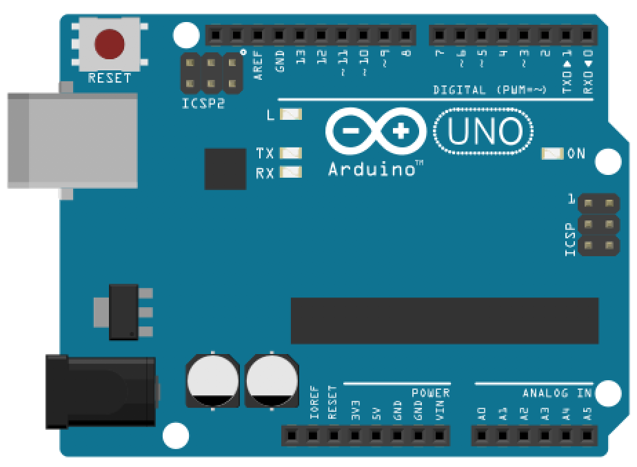 |  |  |
| Arduino Uno, Leonardo, or similar | Red LED | 220Ω Resistor |
Making the circuit
Using the same resistor-wrapped red LED from before, plug the anode + resistor side into Pin 3 and the cathode into GND. See the wiring diagram below:
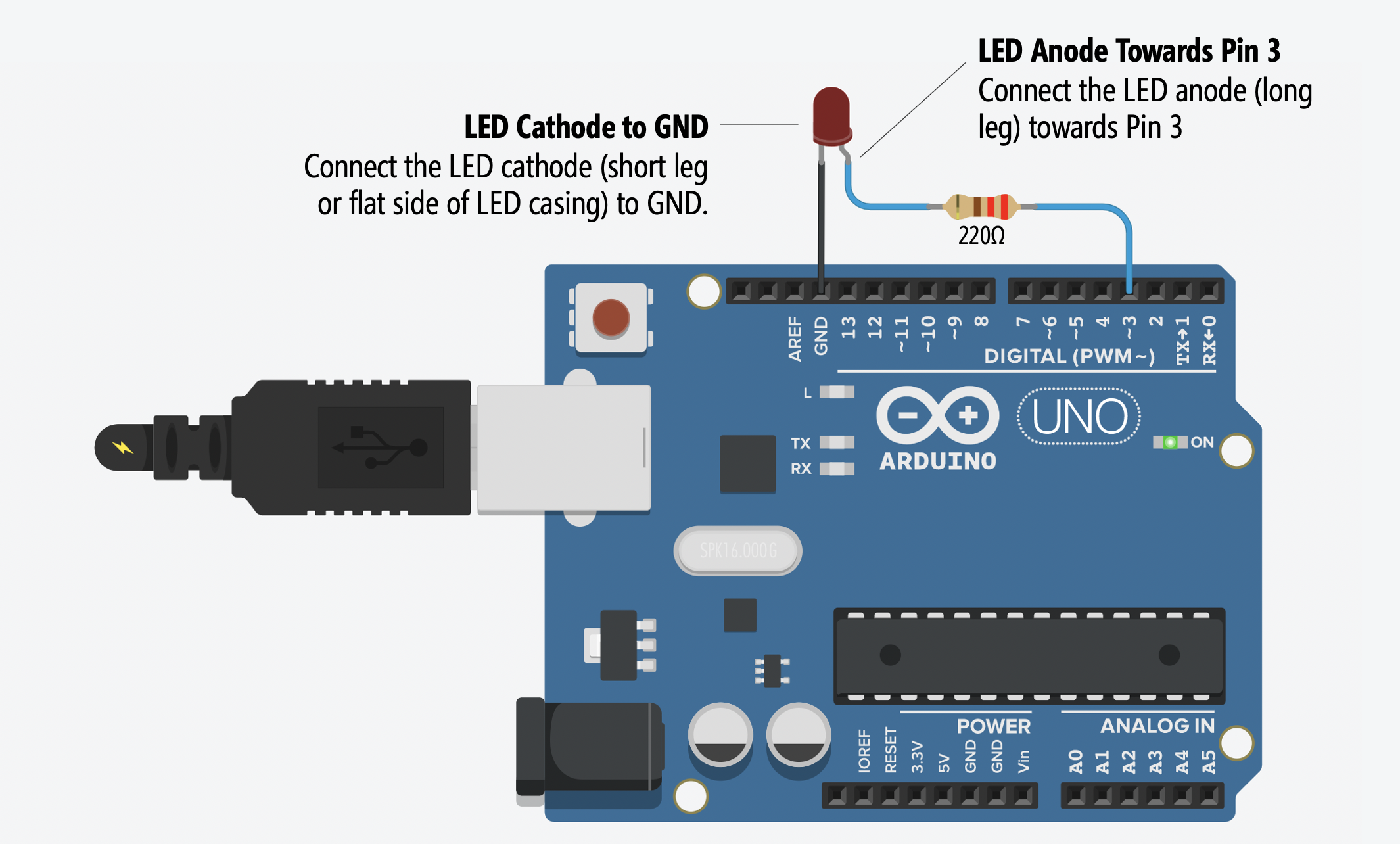
TIP: Double check to make sure that you’ve correctly connected GND and Pin 3. When building circuits, it’s easy to be “off-by-one” pin (a frustrating error!).
While it’s not necessary to use a breadboard for this simple circuit, here are two functionally equivalent breadboard-based wiring options. As our circuits get more complex, you will need to use a breadboard—so it’s good to start (or continue!) building up familiarity. Which breadboarded design makes most sense to you? Use your finger to trace the flow of current from Pin 3 to GND. To zoom in on the images, you can right click and select “Open Image in a New Tab.”
| Breadboard Option 1 | Breadboard Option 2 |
|---|---|
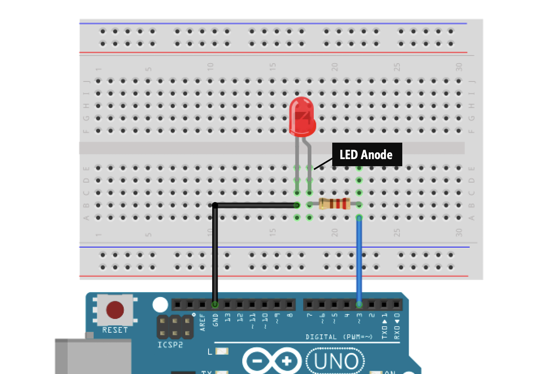 | 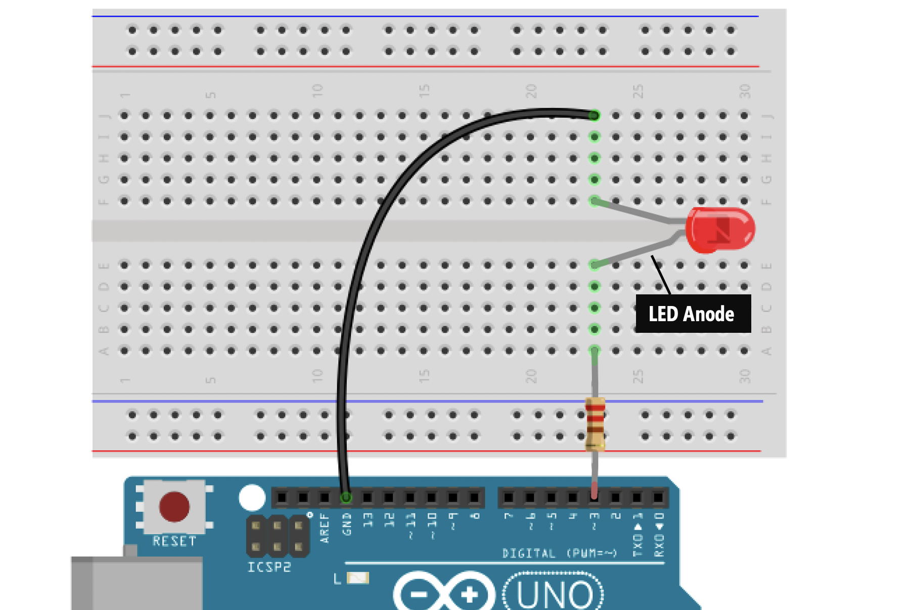 |
You can always return to our breadboard lesson to refresh your memory!
Next, we’ll write C/C++ code for the Arduino’s microcontroller to turn on the LED from Pin 3, which will programmatically set Pin 3 to 5V.
The Arduino software is open source and consists of a development environment (called an IDE) and core libraries. The core libraries are written in C and C++ and compiled using avr-gcc and AVR libc. The source code for Arduino is hosted on GitHub. The core libraries for AVR microcontrollers—such as the ATmega328P (which the Arduino Uno uses) and the ATmega32U4 (which the Arduino Leonardo uses)—are shared in the ArduinoCore-avr GitHub repository.
Get the Arduino IDE
But first, we need to download and install the Arduino IDE (if you haven’t already). Please follow our step-by-step installation and customization instructions here.
Introducing digital output
Now, we are going to write code to turn on our LED by setting Pin 3 to HIGH (or 5V). Then, we will modify this code to flash the LED both on and off. To do this, we have to introduce digital output.
The Arduino Uno has 20 general-purpose input/output (GPIO) pins that can be used for digital input/output (I/O)—that is, to read or write digital information (HIGH or LOW) using digitalRead() and digitalWrite(), respectively.
We could have selected any of these pins for this lesson but we chose Pin 3 (in part, because we want to use this same pin in Lesson 4 and using it now simplifies things!).
You can control any of these 20 digital I/O pins with three functions:
pinMode(int pin, int mode)configures a specified pin as either anINPUTorOUTPUT. In this case, we want to specifyOUTPUTbecause we want to output a signal to turn on the LED.digitalRead(int pin)reads digital input from the specified pin, eitherHIGHorLOW. We will coverdigitalReadin our Intro to Input lesson series.digitalWrite(int pin, int value)writes digital output to the specified pin, eitherHIGHorLOW. We’ll be usingdigitalWritein this lesson.
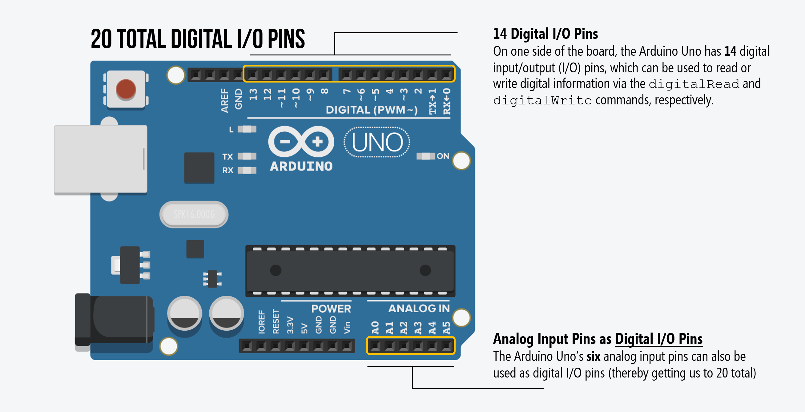
How did we count 20 digital I/O pins?
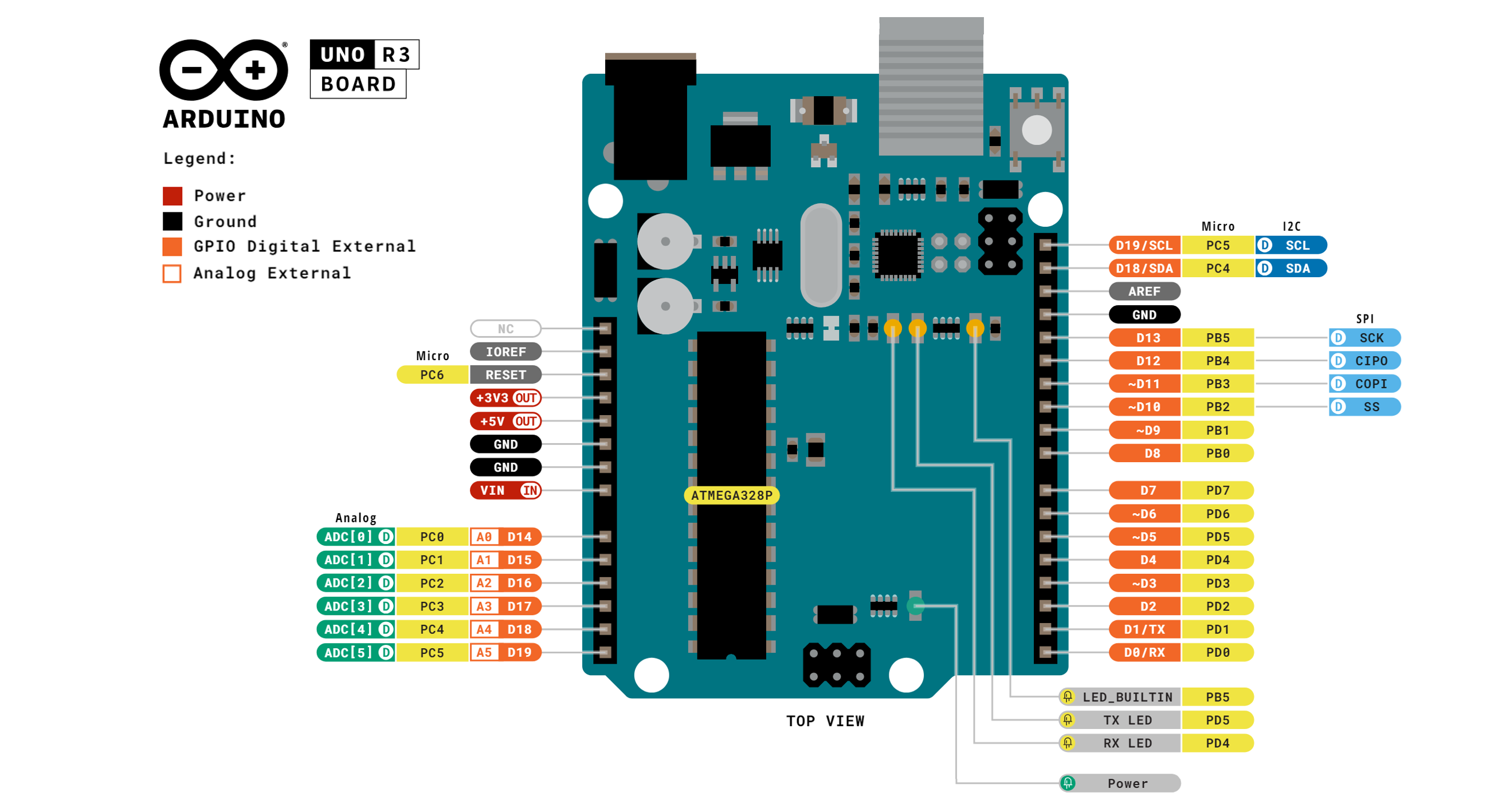
While the white silkscreening on the Uno and Leonardo makes it seem like these boards only have 14 digital I/O pins (the top part of the board), they in fact have 20! Indeed, you can consult the official Arduino Uno pinout diagram for verification.
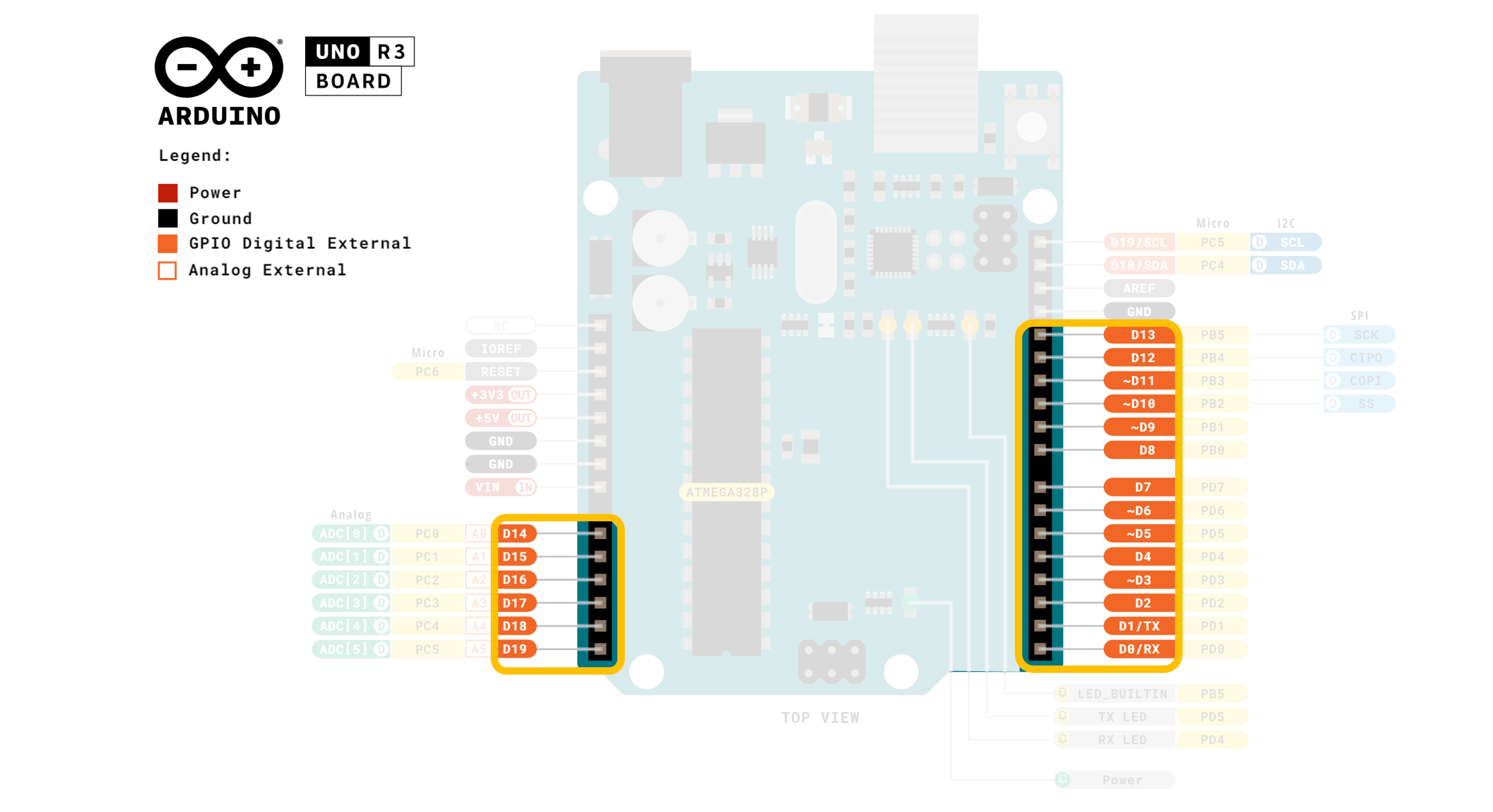
And here’s a version with the digital I/O pins highlighted for emphasis:
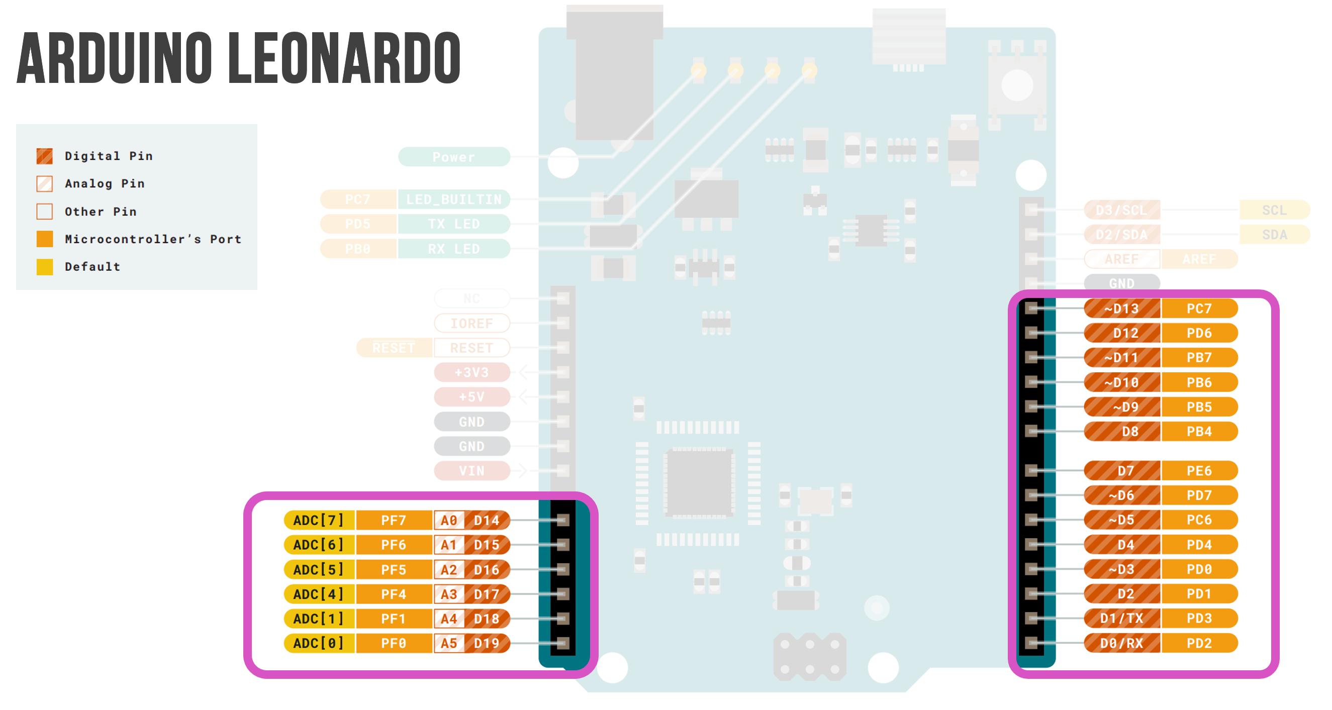
It’s the same with the Arduino Leonardo (see official pinout diagram here):
Finally, here’s a Tinkercad Circuit simulation demonstrating the use of all 20 digital I/O pins as digital output.
Figure. A Tinkercad Circuit simulation showing how to use all 20 GPIO pins as digital output on the Arduino Uno. You can try the simulation yourself here and view the code on GitHub here.
What do we mean by HIGH and LOW?
An Arduino’s supply voltage is often written as \(V_S\), \(V_{CC}\), and \(V_{DD}\) in datasheets. Sadly, there does not appear to be a consistent naming convention (link1, link2). We’ll try to consistently use \(V_{CC}\) or \(V_S\) but occasionally you’ll see others (e.g., \(V_{DD}\)).
On the Arduino Uno and Leonardo, the supply voltage (\(V_{CC}\)) is 5V. So, when a pin is configured as an output via pinMode(<pin>, OUTPUT), the pin can provide either a HIGH voltage (\(V_{CC}\)) or a LOW voltage (0V). Some microcontrollers operate at 3.3V. In this case, a HIGH state would be 3.3V but a LOW state would still be 0V.
We’ll look at actual digital output signals on an oscilloscope later in this lesson (in the section “What does digital output look like?”).
What can we use digital output pins for?
In general, digital output pins on microcontrollers are designed to send control signals and not act as power supplies. So, while these pins can supply enough current to use LEDs, piezo speakers, or control servo motors, if you need to control a high-current DC load such as a DC motor, you’ll need to use a transistor—which is an electronically controlled switch.
NYU’s ITP course has a nice tutorial on how to use a transistor, external power supply, and an Arduino to drive a DC motor. For students enrolled in our courses, we will tell you when you would need to do this. Rest assured, none of the introductory lessons require this circuit configuration.
What’s the maximum amount of current a digital output pin can supply?
The Arduino Uno uses the ATmega328P microcontroller and the Leonardo uses the ATmega32U4—both which can supply an absolute maximum of 0.04A (40 mA) per digital output pin or about ~4 LEDs in parallel (with 10mA per branch).
According to Section 28.1 in the ATmega328P datasheet, anything beyond these limits “may cause permanent damage to the chip”. The maximum total current draw across all I/O pins together should not exceed 200mA. This is the same limit for the ATmega32U4.
Again, this limit is not a concern for our introductory lessons (unless you deviate significantly from them).
Importantly, once you configure a digital I/O pin as OUTPUT, do not connect it directly to GND or \(V_{CC}\) or you may damage the microcontroller (typically, just that particular pin will be damaged). So, for example, if you’ve accidentally connected Pin 3 directly to 5V and write pinMode(3, OUTPUT); digitalWrite(3, LOW);, a whole bunch of current will “sink” into Pin 3 and potentially damage the pin.
You may be thinking: “um, what?” That’s OK. In our years of teaching, we have had very few Arduinos damaged due to current overdraw (though it’s worth watching this video on “5 Ways to Destroy an Arduino”). And you won’t need to worry about these limits for any of the introductory lessons.
Internally, how does the Arduino set a pin HIGH or LOW?
Though it’s not necessary to understand the following in order to use an Arduino, you might be curious about how the Arduino controls the voltage output of a pin. Understanding this also helps explain why you shouldn’t connect an output pin directly to \(V_{CC}\) or GND. The answer: transistors. As the (simplified) schematic below highlights, a digital output pin provides either \(V_{DD}\) (5V on the Uno and Leonardo) or \(GND\) (0V) by dynamically turning on/off transistors (an inverter ensures that only one transistor can be on at a time).
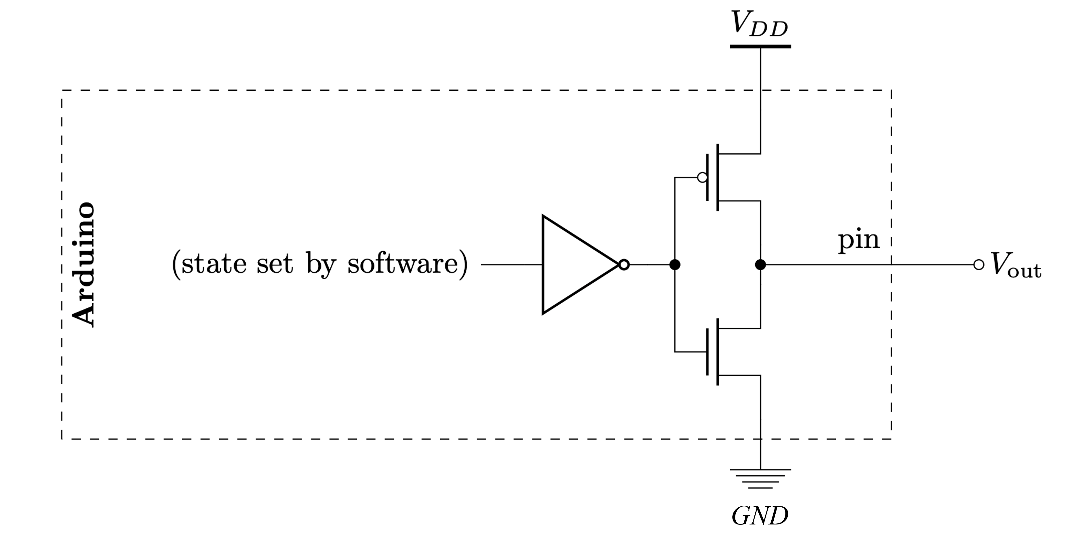 Figure. Schematic by Chuan-Zheng Lee for his “Intro to Arduino” course at Stanford.
Turn on LED programmatically via Pin 3
OK, so let’s write an initial program to set Pin 3 to HIGH (5V). We’re not blinking yet—just using code to set Pin 3’s output voltage to \(V_{CC}\).
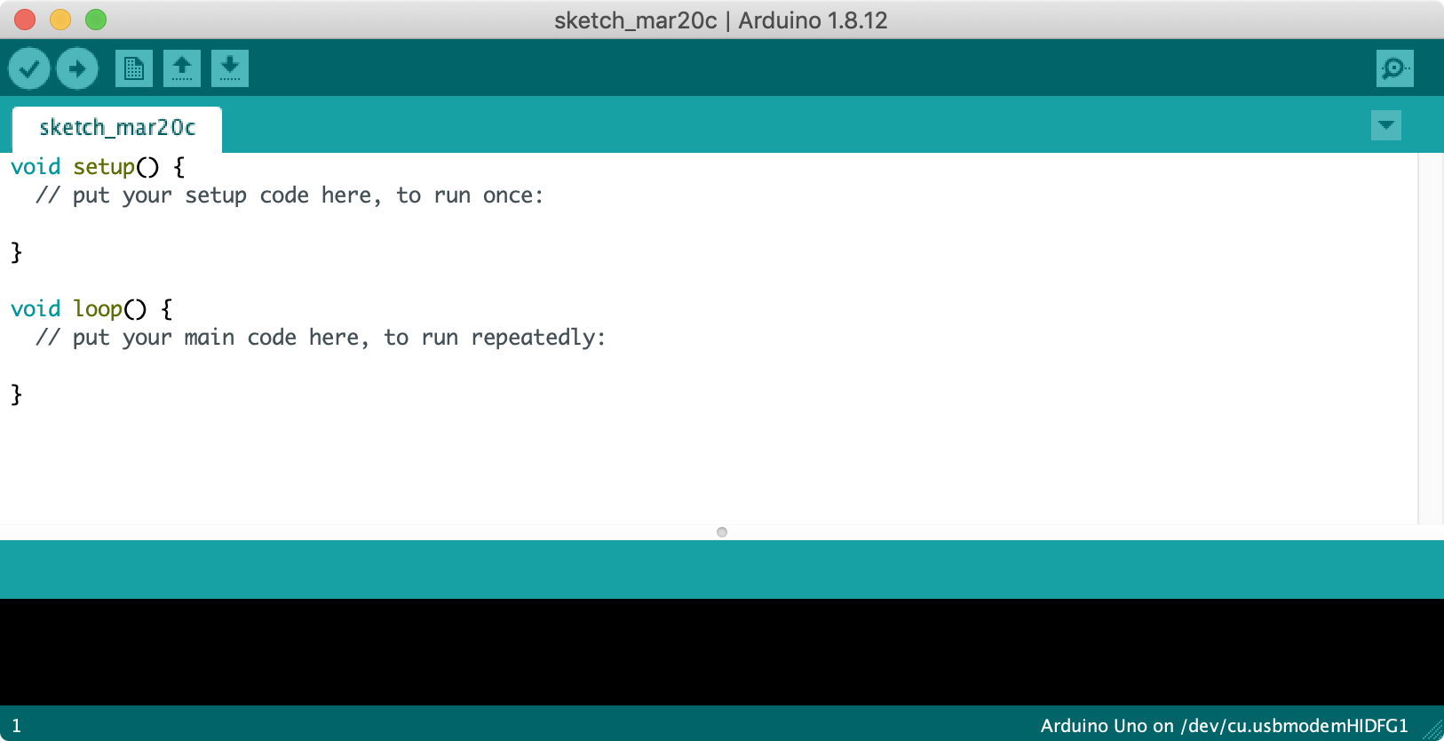
Step 1: Start a new sketch in the Arduino IDE
Start a new sketch in the Arduino IDE:
Step 2: Set the pinMode for Pin 3
Because the 20 digital I/O pins can be used for either input or output, we need to specify that Pin 3 should be used for output. That is, we want the Arduino to output a 5V signal on Pin 3 to turn on our LED. We configure pins in the setup() block and use the pinMode(int pin, int mode) command, which takes in a pin as the first parameter and a mode (INPUT or OUTPUT) as the second.
void setup() {
  // put your setup code here, to run once:
  pinMode(3, OUTPUT);
}
Step 3: Set Pin 3 HIGH
Lastly, we need to actually set the Pin 3 signal to HIGH. For this, we use the digitalWrite(int pin, int value) command, which takes in a pin as the first parameter and a value (HIGH or LOW) as the second. We could do this either in setup() or in loop() but since we’re not currently changing the output signal, there is no reason to put it in loop(), so let’s put it in setup() along with the pinMode code.
void setup() {
  // put your setup code here, to run once:
  pinMode(3, OUTPUT);
  digitalWrite(3, HIGH); // turn LED on (output 5V)
}
Step 4: Compile the code
We did it! Now it’s time to compile and upload the code to Arduino.
Compile the code by clicking on the “verify” checkmark button in the upper-left corner of the Arduino IDE. If you haven’t already, the Arduino IDE will also ask you to save your sketch. If there are any syntax or other identifiable errors in the code, the Arduino IDE will print them out in the console window at the bottom.
Step 5: Upload the code to Arduino
Finally, upload the code to the Arduino by clicking on the “right arrow” button (next to verify). Importantly, you must have already set your Arduino board and port in Tools->Board and Tools->Port, respectively.
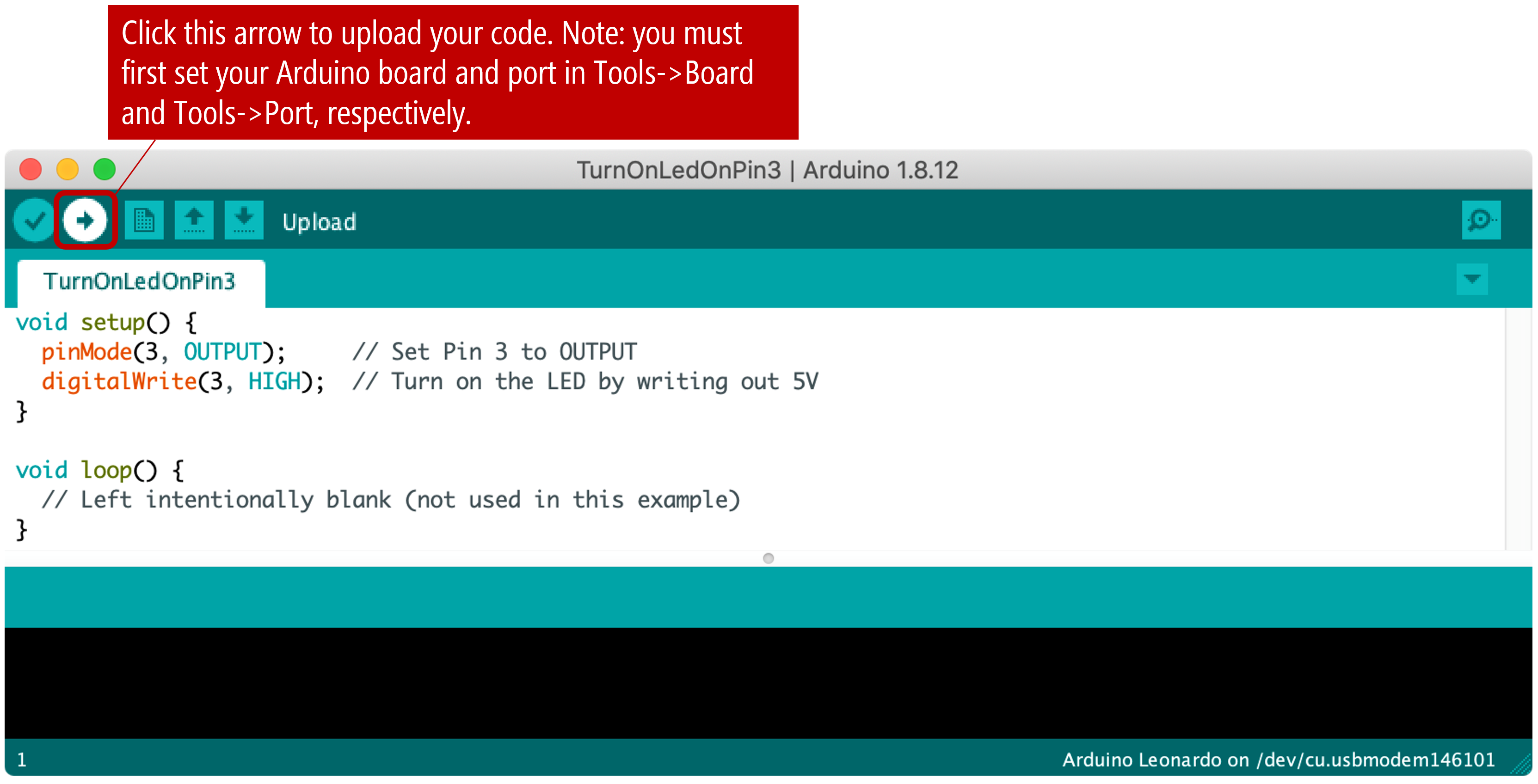
Once uploading is complete, the code automatically runs on the Arduino and the LED should immediately turn on!
Figure. Uploading and running the LED-on code on an Arduino Uno. Note: on my Windows machine, I use a dark theme for the Arduino IDE. Since the 2.x version of the IDE, there are several pre-installed dark themes.
Here’s an illustrative animation of what’s happening in your circuit when the Arduino drives Pin 3 HIGH—hopefully, this matches your conceptual understanding as well:
Turn on and off the LED programmatically via Pin 3
Now, let’s modify our code to turn on and off the LED programmatically. More specifically, we will alternate between having the LED on for one second and having the LED off for one second. To do this, we’ll use the delay(int ms) function, which pauses the program for the specified amount of time (in milliseconds).
Step 1: Move the digitalWrite code from setup() to loop()
First, move the digitalWrite code from setup() to loop():
void setup() {
  // set Pin 3 to output
  pinMode(3, OUTPUT);
}

void loop() {
  digitalWrite(3, HIGH);  // turn LED on (output 5V)
}
Step 2: Add in delays and code to turn off LED
Now, add in code to pause (for one second) and then turn off the LED (for one second) using delay(). Remember, when loop() completes, it is automatically called again (making the LED blink continuously).
void setup() {
  // set Pin 3 to output
  pinMode(3, OUTPUT);
}

void loop() {
  digitalWrite(3, HIGH);  // turn LED on (output 5V)
  delay(1000);            // wait one second
  digitalWrite(3, LOW);   // turn LED off (output 0V)
  delay(1000);            // wait another second
}
Step 3: Compile and upload
We’re done! Now, compile and upload the code and see it run!
Step 4: Replace constants
Typically, we want to limit the use of literal constants in our code and replace them by variables. In this case, let’s replace 3 with LED_OUTPUT_PIN defined as a global variable at the top of our program (const int LED_OUTPUT_PIN = 3;). This will make our code more maintainable, more readable, and less prone to accidental mistakes. Try to do this for all literals in the future.
const int LED_OUTPUT_PIN = 3;
void setup() {
  // set Pin 3 to output
  pinMode(LED_OUTPUT_PIN, OUTPUT);
}

void loop() {
  digitalWrite(LED_OUTPUT_PIN, HIGH);  // turn LED on (output 5V)
  delay(1000);                         // wait one second
  digitalWrite(LED_OUTPUT_PIN, LOW);   // turn LED off (output 0V)
  delay(1000);                         // wait another second
}
Walking through the code
How does this work? See the code walkthrough video below. The key idea is that setup() runs once to configure Pin 3 as output, then loop() runs repeatedly: it sets Pin 3 HIGH (turning the LED on), waits one second, sets Pin 3 LOW (turning the LED off), waits another second, and then loop() is automatically called again—creating a continuous blink.
Our Blink code is in GitHub
You can access our Blink code in our Arduino GitHub repository. A “live” version is also embedded directly from the GitHub repo below.
This source code is on GitHub.
What does the digital output look like?
A common and important question when first working with microcontrollers is: what does the digital output look like?
In your mind, imagine what the voltage out of Pin 3 looks like over time (the x-axis is time and the y-axis is voltage output). You should envision a 5V output signal HIGH for the delay length followed by a 0V output signal, which is LOW delay length. Indeed, this type of graph is exactly what an oscilloscope is for—it graphs voltage values over time.
Using Tinkercad Circuits, we built the same LED-based circuit as above running the Blink program and hooked it up to an oscilloscope. Then, we recorded different delay values (400, 200, and 50) and created this movie. Is the graph what you expected? Why or why not? We suggest opening the video in its own tab or viewing it in fullscreen to see the details.
Figure. A video of this Tinkercad project with three different delay values for both HIGH and LOW: 400, 200, and 50.
We encourage you to play with this Tinkercad project yourself and investigate different delays and their output on the oscilloscope.
Setting and visualizing different blinking frequencies
We duplicated the above Tinkercad setup (circuit + oscilloscope) in our laboratory and recorded a video. Notably, we used slightly different code that allows us to set the blink frequency by rotating a potentiometer.
Figure. A video showing the digital output voltage waveform at different “blinking” frequencies.
You can play with the Tinkercad version of this experiment here:
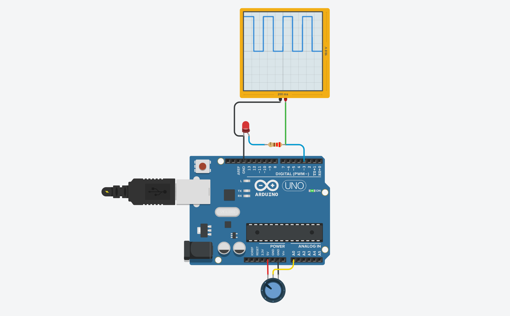 Figure. Tinkercad Circuits version of the settable delay circuit+code (link).
Mental model check: code is loaded and running on the Arduino
As a quick mental model check, it’s worth emphasizing that once you upload the code to your Arduino, you no longer need the USB cable. Why? Because a compiled version of the code is stored locally on your Arduino and stays there even when the Arduino loses power. Your Arduino is the computer! So, you could use some other power source like a 9V battery plugged in to the barrel jack port.
Note: when you upload a new program, it replaces the previous one—only one program can be stored on the Arduino at a time. You don’t need to manually erase the old program first.
Blink without using delay()
Before moving on, it’s worth emphasizing that, in general, long delay() calls should be avoided. Why? Because while in a delay(), the Arduino is no longer responsive. So, for example, imagine updating your Blink program to also react to a button press from the user. If the user happens to press the button while the Arduino is in a delay(), your program would never be able to process that a button was pressed! This is a problem.
It’s OK to stop here and move on to the next lesson. It’s sufficient to be aware that long
delay()calls can be dangerous and should probably be avoided. However, if you’re curious, you can continue this sub-section to see a Blink example that works without delays. We will return to this concept for our final Intro to Output lesson on multi-rate blinking LEDs.If you want to know how
delay()actually works, read “What does delay() actually do” in our Inside Arduino guide.
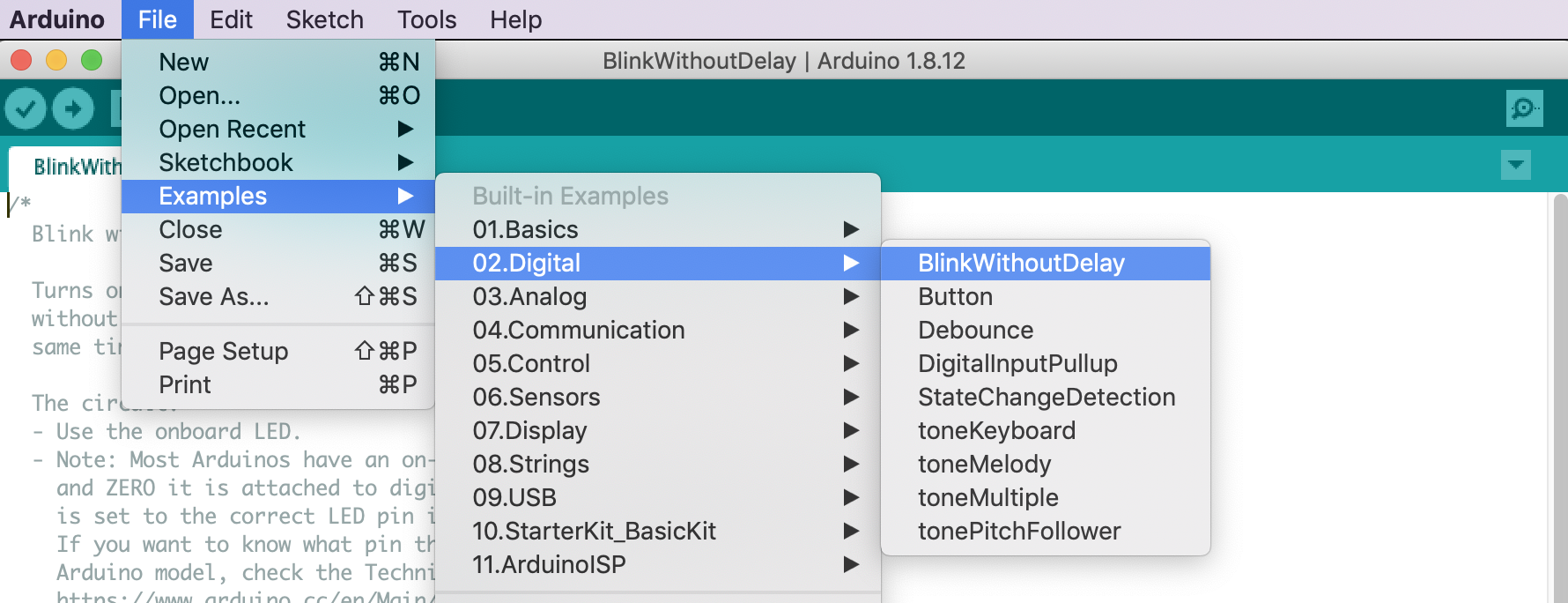
Because delay() usage can be so troublesome, as part of their introductory tutorial series, Arduino publishes another Blink example with a tutorial called BlinkWithoutDelay. As with the regular Blink, this example can be accessed directly in the Arduino IDE:
To avoid delay() calls, the code tracks time, LED state changes (when the LED switches from HIGH to LOW or LOW to HIGH), and when these state changes occur. The BlinkWithoutDelay main loop is below. Notice that there are no delay() calls!
void loop() {
  // check to see if it's time to blink the LED; that is, if the difference
  // between the current time and last time you blinked the LED is bigger than
  // the interval at which you want to blink the LED.
  unsigned long currentMillis = millis();

  if (currentMillis - previousMillis >= interval) {
    // save the last time you blinked the LED
    previousMillis = currentMillis;

    // if the LED is off turn it on and vice-versa:
    if (ledState == LOW) {
      ledState = HIGH;
    } else {
      ledState = LOW;
    }

    // set the LED with the ledState of the variable:
    digitalWrite(ledPin, ledState);
  }
}
We’ve also made our own BlinkWithoutDelay version, which is available on GitHub and shown below. This version is functionally equivalent to Arduino’s official example but uses our own coding style and is, in our opinion, more understandable.
This source code is on GitHub.
Exercises
Want to go further? Here are some design challenges to reinforce what you’ve learned:
- Change the blink rate. Modify the
delayvalues to 250ms or 100ms. At what point does the blinking become imperceptible to your eye? - Asymmetric blink. Try using different delay values for
HIGHandLOW(e.g., 200ms on, 800ms off). How does this change the perceived brightness? - Morse code. Can you make the LED blink out “SOS” in Morse code (three short blinks, three long blinks, three short blinks)?
Lesson Summary
In this lesson, you wrote your very first Arduino program! You learned:
- How to configure a digital I/O pin as an output using
pinMode(). - How to programmatically set a pin to 5V (
HIGH) or 0V (LOW) usingdigitalWrite(). - How to use
delay()to pause program execution and create a blinking effect. - What a digital output signal actually looks like when viewed on an oscilloscope.
- Why relying heavily on
delay()can be problematic for more complex, responsive programs.
Next Lesson
In the next lesson, we are going to learn about a few basic debugging strategies using Serial.print() before moving on to analog output, which lets us control the output voltage not just at two levels, LOW (0V) or HIGH (5V), but at finer levels between 0 and 5V using analogWrite(int pin, int value).