Lesson 1: Intro to the ESP32
Table of Contents
- What is the ESP32?
- ESP32 vs. Arduino: comparison table
- The Adafruit ESP32-S3 Feather
- ESP32-S3 Feather pin diagram
- Setting up the Arduino IDE
- Resources
- Summary
- Exercises
- Next Lesson
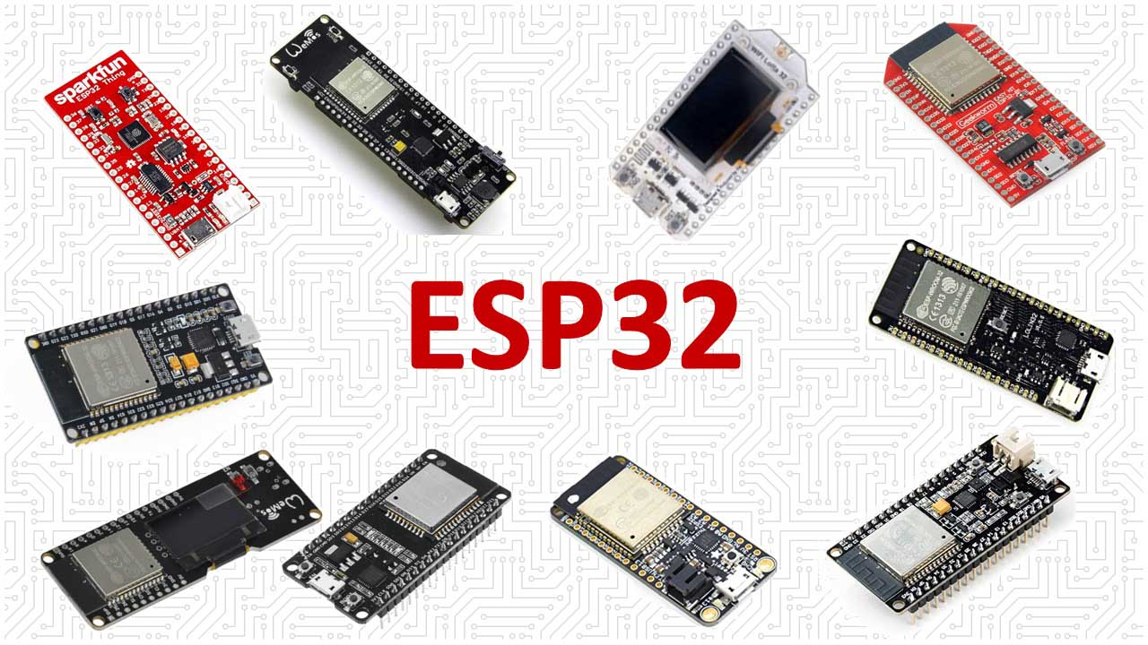 Figure. There are dozens of ESP32 development boards from Espressif, Adafruit, SparkFun, and others. Image from makeradvisor.com.
In this lesson, you will learn:
- What the ESP32 is and how it compares to the Arduino Uno and Leonardo
- Key differences between the original ESP32 and the ESP32-S3
- Why the ESP32 operates at 3.3V (not 5V) and why this matters
- How to identify pins on the Adafruit ESP32-S3 Feather
- How to set up the Arduino IDE to program your ESP32
What is the ESP32?
The ESP32 is a low-cost “system-on-a-chip” (SoC) with integrated WiFi, Bluetooth, and a powerful microprocessor, created by Espressif Systems. The original ESP32, released in 2016, succeeded Espressif’s hugely popular ESP8266 and brought dual-core processing, Bluetooth support, and many more peripherals.
Since then, Espressif has released an entire family of ESP32 variants—each optimized for different use cases. The family now includes eleven SoCs: the original ESP32, the S-series (S2, S3) for high-performance applications, the C-series (C2, C3, C5, C6) for cost-effective RISC-V-based IoT, the H-series (H2, H4) for Thread/Zigbee mesh networking, and the P4 for multimedia. See Espressif’s product comparison tool for details.
For our lessons, we focus on two boards:
-
Adafruit ESP32-S3 Feather (4MB Flash, 2MB PSRAM) — our primary board for Spring 2026. It features a dual-core 240 MHz Tensilica LX7 processor, native USB-C, WiFi, Bluetooth LE 5.0, a STEMMA QT connector, an onboard NeoPixel, and a LiPoly battery monitor.
-
Adafruit Huzzah32 ESP32 Feather — uses the original ESP32 (dual-core Tensilica LX6). Our earlier Fritzing diagrams and videos reference this board. The concepts and code transfer directly to the S3.
What does “system-on-a-chip” mean? A system-on-a-chip (SoC) integrates the essential components of a computer system—processor, memory, I/O, and often wireless radios—onto a single silicon chip. The ESP32 packs a dual-core 32-bit processor, RAM, WiFi and Bluetooth radios, and advanced peripherals (like touch sensors and cryptographic hardware) into one tiny package. This high integration drastically reduces manufacturing complexity, which is why a complete ESP32 module can cost just a few dollars and full development boards are typically under $20. For more on how chips, modules, and development boards relate, see the module overview.
How does this compare to the Arduino Uno? In contrast, the Uno’s brain—the ATmega328P—is a traditional microcontroller (MCU). While it also integrates a CPU, memory, and basic I/O on one chip, it lacks WiFi, Bluetooth, and advanced peripherals. The 8-bit ATmega328P MCU is designed for simple, single-threaded control tasks, such as reading a sensor, toggling a relay, controlling a short LED strip, or driving a small display. To add WiFi to an Uno, you have to attach a separate, comparatively expensive networking chip or “shield.”
ESP32 vs. Arduino: comparison table
Here’s a side-by-side comparison of the Arduino Uno Rev3, the original ESP32, and the ESP32-S3. Data derived from Espressif’s official documentation.
The ESP32 runs at 3.3V, not 5V like the Arduino Uno and Leonardo. This means GPIO pins output 3.3V when HIGH and expect no more than 3.3V as input. You can accidentally apply 5V to a GPIO pin in several ways: connecting a 5V sensor or module directly (many Arduino-oriented breakout boards output 5V logic), wiring a pin to the USB 5V rail (like the USB pin on your Feather), or using a voltage divider that doesn’t step down far enough. Applying 5V to a GPIO pin can permanently damage the chip. If you need to interface with 5V devices, use a level shifter or a voltage divider to bring the signal down to 3.3V. The good news: most common components we use in this course (LEDs, potentiometers, piezo buzzers, basic resistive sensors) work fine at 3.3V with no extra hardware.
General features
| Feature | Arduino Uno | ESP32 (original) | ESP32-S3 |
|---|---|---|---|
| Launch year | 2010 | 2016 | 2020 |
| Core | 8-bit ATmega328P | Xtensa® dual-core 32-bit LX6 | Xtensa® dual-core 32-bit LX7 |
| Typical frequency | 16 MHz | 240 MHz | 240 MHz |
| Operating voltage | 5V | 3.3V | 3.3V |
| Wi-Fi | ✖️ | 802.11 b/g/n, 2.4 GHz | 802.11 b/g/n, 2.4 GHz |
| Bluetooth | ✖️ | Bluetooth v4.2 (Classic + BLE) | Bluetooth 5 (LE only) |
| Native USB | ✖️ | ✖️ | ✅ (USB OTG) |
| SRAM | 2 KB | 520 KB | 512 KB |
| Flash | 32 KB | Up to 4 MB | Up to 8 MB |
| PSRAM | ✖️ | ✖️ (optional external) | Up to 8 MB (2 MB on Feather) |
| Datasheet | ATmega328P (PDF) | ESP32 (PDF) | ESP32-S3 (PDF) |
Key peripherals
| Peripheral | Arduino Uno | ESP32 (original) | ESP32-S3 |
|---|---|---|---|
| ADC | One 10-bit, 6 channels | Two 12-bit, 18 channels | Two 12-bit, 20 channels |
| DAC | ✖️ | Two 8-bit channels | ✖️ |
| Touch sensor | ✖️ | 10 | 14 |
| GPIO | 14 | 34 | 45 |
| LED PWM channels | 6 (via timers) | 16 | 8 |
| SPI | 1 | 4 | 4 |
| I2C | 1 | 2 | 2 |
| UART | 1 | 3 | 3 |
A few things to note from these tables:
- ADC (Analog-to-Digital Converter): Converts an analog voltage to a digital number. The ESP32’s ADCs are 12-bit (values range from 0–4095) compared to the Uno’s 10-bit ADCs (0–1023). Make sure you use the correct maximum value in functions like
map(). You’ll use the ADC in Lesson 4. - DAC (Digital-to-Analog Converter): Outputs a true analog voltage (not PWM). The original ESP32 has two DAC channels for true analog output; the ESP32-S3 does not have a DAC. If you need analog output on the S3, use PWM with a low-pass filter or an external DAC like the MCP4725.
- Touch sensor: Built-in capacitive touch sensing hardware—no external components needed. The ESP32-S3 has 14 capacitive touch sensing pins—we’ll use these in Lesson 6.
- LED PWM (LEDC): The ESP32’s dedicated PWM peripheral for dimming LEDs, driving motors, and generating tones. Unlike the Uno (which has 6 PWM pins), all ESP32 GPIO pins can do PWM, though there are a limited number of independent PWM channels. You’ll learn the LEDC API in Lesson 3.
- SPI / I2C / UART: Standard communication buses for connecting to sensors, displays, and other devices. SPI is fast (displays, SD cards), I2C is simple (sensors, OLEDs), and UART is serial communication (
Serial.print()uses UART). The ESP32 has more of each than the Uno. - FPU (Floating Point Unit): The ESP32 has a hardware floating point unit for fast math. On the ESP32-S3, the FPU supports both single and double precision—the Arduino Uno has no FPU and must emulate floating point in software, which is much slower.
The Adafruit ESP32-S3 Feather
For our course, we use the Adafruit ESP32-S3 Feather with 4MB Flash and 2MB PSRAM. Here’s how it compares to the Arduino Uno and the older ESP32 (Adafruit Huzzah32):
| Arduino Uno | Huzzah32 (ESP32) | ESP32-S3 Feather | |
|---|---|---|---|
| Image | 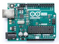 | 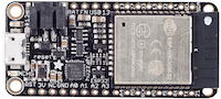 | 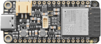 |
| Store | Arduino | Adafruit | Adafruit |
| Microcontroller | 8-bit, 16 MHz ATmega328P | 32-bit, 240 MHz dual-core LX6 | 32-bit, 240 MHz dual-core LX7 |
| Operating voltage | 5V | 3.3V | 3.3V |
| Flash memory | 32 KB | 4 MB | 4 MB |
| SRAM | 2 KB | 520 KB | 512 KB + 2 MB PSRAM |
| GPIO pins | 14 | 21 | 21 |
| PWM pins | 6 | All | All |
| Analog inputs | 6 | 13 (A0–A12) | 6 (A0–A5) |
| Wi-Fi | ✖️ | 802.11 b/g/n | 802.11 b/g/n |
| Bluetooth | ✖️ | Classic + BLE | BLE 5.0 only |
| USB connection | Type-B | Micro-USB | USB-C (native) |
| Battery monitor | ✖️ | Via voltage divider on A13 | MAX17048 over I2C |
| NeoPixel | ✖️ | ✖️ | ✅ (1 onboard) |
| STEMMA QT | ✖️ | ✖️ | ✅ |
As we discuss in the module overview, you can find far cheaper ESP32 boards online—our lessons work with any of them. We use Adafruit’s Feather boards for their reliable build quality, thorough documentation, and the Feather ecosystem of stackable expansion boards (“FeatherWings”) like the MP3 Player, GPS, and DC Motor FeatherWings.
Powering the ESP32-S3 Feather
The ESP32-S3 Feather is not designed for external power supplies. Power it only via USB-C (5V) or a LiPoly battery (3.7/4.2V) connected to the JST port. Do not use a 9V battery—you will damage your board!
The ESP32-S3 Feather has a built-in LiPoly battery charger. When USB is plugged in, the battery charges automatically. The onboard MAX17048 battery monitor—added by Adafruit on the Feather board, not part of the ESP32-S3 chip—reports voltage and charge percentage over I2C. The charge LED (yellow) lights when charging and turns off when complete. If no battery is plugged in, the charge LED may blink rapidly—this is harmless.
ESP32-S3 Feather pin diagram
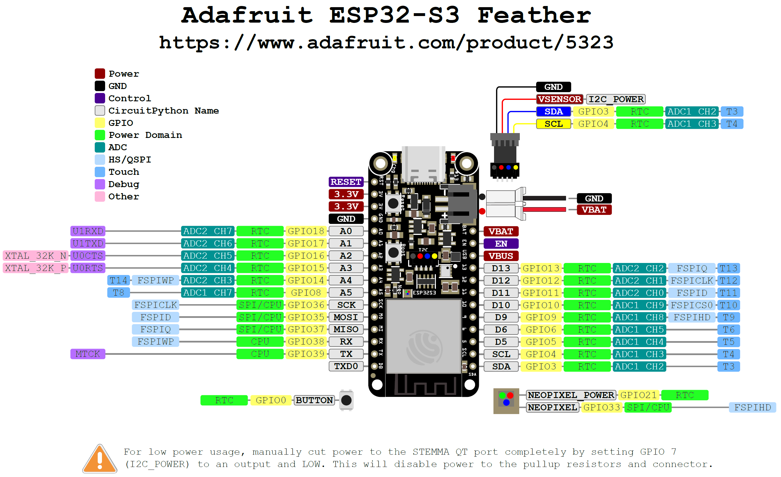 Figure. A pin diagram for the Adafruit ESP32-S3 Feather. You may want to right click and select “Open image in new tab” to see a full-size version. See also the PDF on Adafruit’s GitHub here.
The pin diagram above is from Adafruit’s official ESP32-S3 documentation. We recommend printing it out or keeping it open on a second monitor—you’ll refer to it constantly! See also the PDF on GitHub for full details.
In our code, we reference pins either by their GPIO number (an integer), their analog input number (prefixed by A, e.g., A0), or their touch number (prefixed by T, e.g., T1) for capacitive touch sensing. You can always use the GPIO number directly.
Important notes for the ESP32-S3 Feather
- The ESP32-S3 runs on 3.3V power and logic. GPIO pins are not 5V safe!
- There are 21 GPIO pins available on the breakout headers. All are output-capable, and all support PWM.
- There are 6 analog input pins (A0–A5). A0–A4 are on ADC2; A5 is on ADC1.
- The ADC resolution is 12 bits (0–4095), compared to the Arduino Uno’s 10-bit ADC (0–1023).
- Pin 13 has a small red LED connected to it (
LED_BUILTIN), just like on the Arduino Uno. - There is an onboard NeoPixel RGB LED. The NeoPixel data pin and power pin are controllable in software for low-power applications.
- The STEMMA QT connector provides plug-and-play I2C for connecting sensors without soldering.
- The ESP32-S3 has native USB, so it appears as a serial port without needing an external USB-to-UART bridge chip. No driver installation is needed on most operating systems.
ADC2 and WiFi
ADC2 is unavailable when WiFi is active. This is a hardware limitation on all ESP32 variants. When you use WiFi, you can only read analog input from ADC1 pins. On the ESP32-S3 Feather, only A5 is on ADC1; A0–A4 are on ADC2. Plan your circuits accordingly—if you need WiFi and analog input simultaneously, use A5 or an external ADC.
Using the Huzzah32 instead? (click to expand)
Huzzah32 pin diagram
The Huzzah32 uses the original ESP32 chip. The pin layout differs from the ESP32-S3 Feather. We created a custom pin diagram:
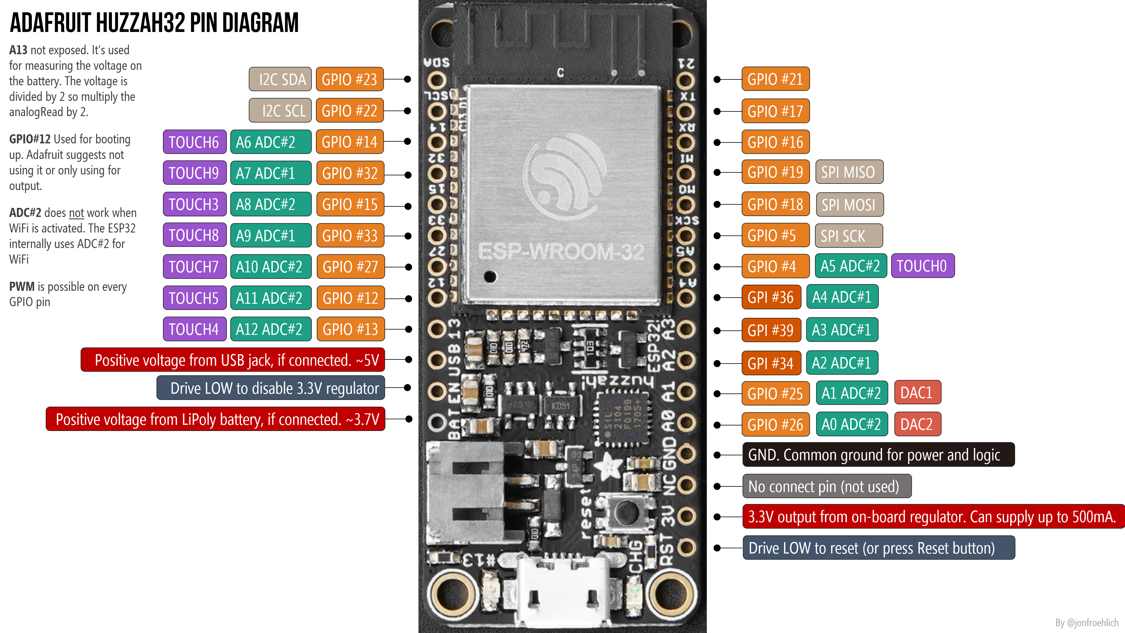 Figure. Custom pin diagram for the Adafruit Huzzah32. See the Adafruit Huzzah32 docs for details.
Huzzah32-specific notes
- The Huzzah32 has 21 GPIO pins, but pins 34 (A2), 39 (A3), and 36 (A4) are input-only (not output-capable). So only 18 GPIO pins work for output.
- The Huzzah32 has 13 analog input pins (A0–A12). A13 is not exposed on the breakout pins—it’s used internally for measuring the LiPoly battery voltage via a voltage divider. When reading battery level with
analogRead(A13), multiply by 2 for the correct reading. Here’s a battery level program. - GPIO 13 is
LED_BUILTIN(the red LED next to the Micro-USB port). - The Huzzah32 uses a CP2104 USB-to-UART bridge chip, so you need to install a driver (see setup instructions below).
- On the Huzzah32, ADC1 has 8 channels (GPIOs 32–39) and ADC2 has 10 channels (GPIOs 0, 2, 4, 12–15, 25–27). ADC2 is unavailable when WiFi is active, so use ADC1 pins for analog input when using WiFi.
- The charge LED will blink rapidly when no LiPoly battery is plugged in—this is harmless.
- Power via USB (max 5V, 1A) or LiPoly battery (3.7/4.2V) only. Do not use a 9V battery!
Figure. The Huzzah32 has 21 GPIO pins, but pins 34, 39, and 36 are input-only. Here, all 21 GPIO pins are set to fade—only 18 produce output.
ESP32 pin list (original ESP32)
The official ESP32 pin list is here:
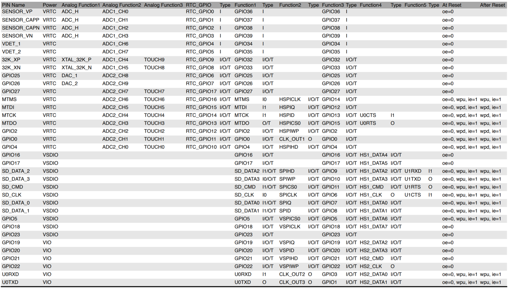 Figure. Screenshot of the ESP32 pin list PDF.
ADC2 and WiFi on the Huzzah32
We empirically tested analog input with and without WiFi active. Check out our two test programs:
- AnalogInputTest.ino reads all analog input pins and prints values to Serial
- WiFiAnalogInputTest.ino extends AnalogInputTest but activates WiFi
In the following video, we test all 13 analog input pins (A0–A12) using a potentiometer for input and the Serial Plotter for output:
Video. Testing all analog input pins on the Huzzah32 with a potentiometer and the Serial Plotter.
Setting up the Arduino IDE
Before you can program the ESP32, you need to install the ESP32 board support package in the Arduino IDE. We’ve put the full setup instructions—including troubleshooting tips—on a separate page:
Already set up? Make sure you have ESP32 Arduino core v3.x installed. The PWM and tone APIs changed significantly between v2 and v3—see the version comparison table.
Resources
Official ESP32 documentation
- ESP-IDF API Reference
- ESP-IDF API Guides
- Arduino core for ESP32 (GitHub)
- Espressif product comparison tool
Adafruit guides
Other
- SparkFun’s ESP32 Thing Hookup Guide — written for SparkFun’s board but has relevant WiFi and BLE examples
- DroneBot Workshop ESP32 Selection Guide (2026) — excellent overview of all ESP32 variants
Summary
In this lesson, you learned about the ESP32 platform—a powerful, WiFi- and Bluetooth-enabled microcontroller family from Espressif. You saw how it compares to the Arduino Uno in terms of speed (240 MHz vs. 16 MHz), memory (512 KB+ vs. 2 KB SRAM), connectivity (WiFi, Bluetooth), and peripherals (12-bit ADC, capacitive touch, native USB on the S3). You also learned the most critical hardware difference: the ESP32 operates at 3.3V, not 5V.
You set up the Arduino IDE with the ESP32 board support package and verified your installation by uploading a test sketch. In the lessons ahead, you’ll use this foundation to blink LEDs, fade lights with PWM, play tones, sense touch, and connect to the internet!
Exercises
Exercise 1: Look up the pin diagram for your ESP32 board (ESP32-S3 Feather or Huzzah32). Identify: (a) which pins support analog input, (b) which pin is LED_BUILTIN, and (c) where the I2C (SDA/SCL) and SPI (MOSI/MISO/SCK) pins are located.
Exercise 2: Upload the built-in Blink example to your ESP32. Modify it to blink at a different rate—say, 100ms on and 900ms off. Verify that it works.
Exercise 3: Open Tools → Board Info (or look at the Serial Monitor output on boot) to find out which version of the ESP32 Arduino core you have installed. Is it version 2.x or 3.x? This matters because the PWM and tone APIs changed between versions—we’ll discuss this in Lesson 3.
Next Lesson
In the next lesson, you will write your first ESP32 program to blink an LED using the ESP32 Arduino library.