Lesson 4: Fading an LED
Table of Contents
- Materials
- Making the circuit
- Using analogWrite
- Writing the code
- Visualizing the voltage output
- Calculating the current through our LED
- Improved fading approach: removing for loop
- Exercises
- Lesson Summary
- Next Lesson
In the previous lesson, we learned how to turn on and off an LED using digitalWrite—which worked by alternately setting Pin 3 to 5V (HIGH) and 0V (LOW). In this lesson, we’ll learn how to programmatically control the output voltage at finer gradations using analogWrite. More specifically, we will gradually fade an LED on and off like the animation below illustrates.
Figure. This illustrative animation doesn’t show current (the yellow circles) only due to my limited animation skills. But hopefully you can visualize (in your mind) how the LED varies in brightness with current just the same. :)
Materials
You will use the same materials as before, including the Arduino IDE and a USB cable to upload your program from your computer to your Arduino.
| Arduino | LED | Resistor |
|---|---|---|
 |  |  |
| Arduino Uno, Leonardo, or similar | Red LED | 220Ω Resistor |
Making the circuit
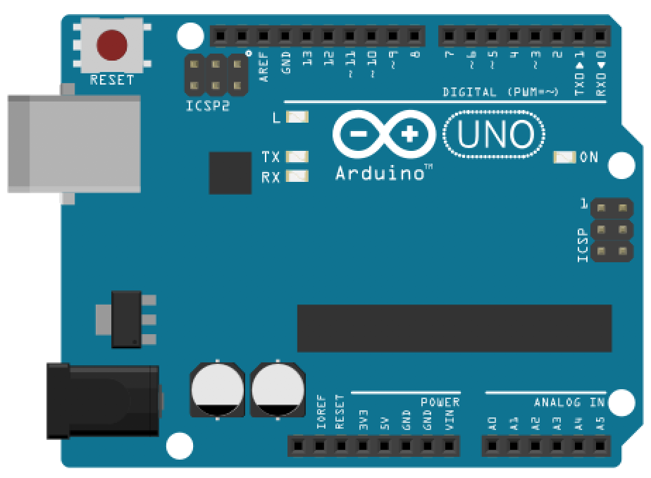
As noted in the “Intro to Digital Output” lesson, the Arduino Uno has 20 general-purpose input/output (GPIO) pins that can be used for digital input/output (I/O) using digitalRead() and digitalWrite(), respectively.
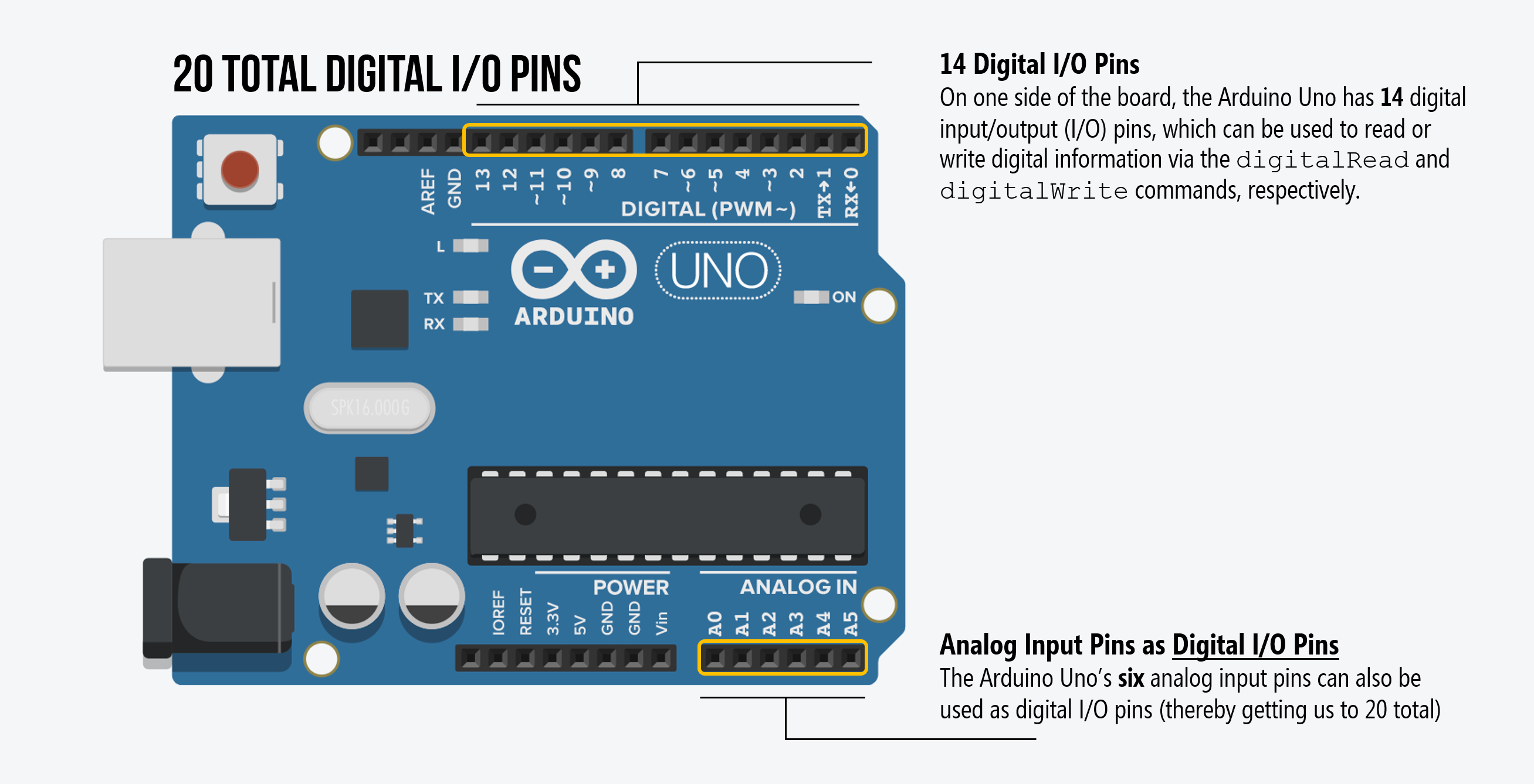
However, 6 of the 20 I/O pins can also be used for “analog” output—voltage output that is not just HIGH (5V) or LOW (0V) but between these two extremes. These analog output pins are indicated by the tilde (~) printed next to the pin on the Arduino (silkscreened directly on the Arduino’s PCB).
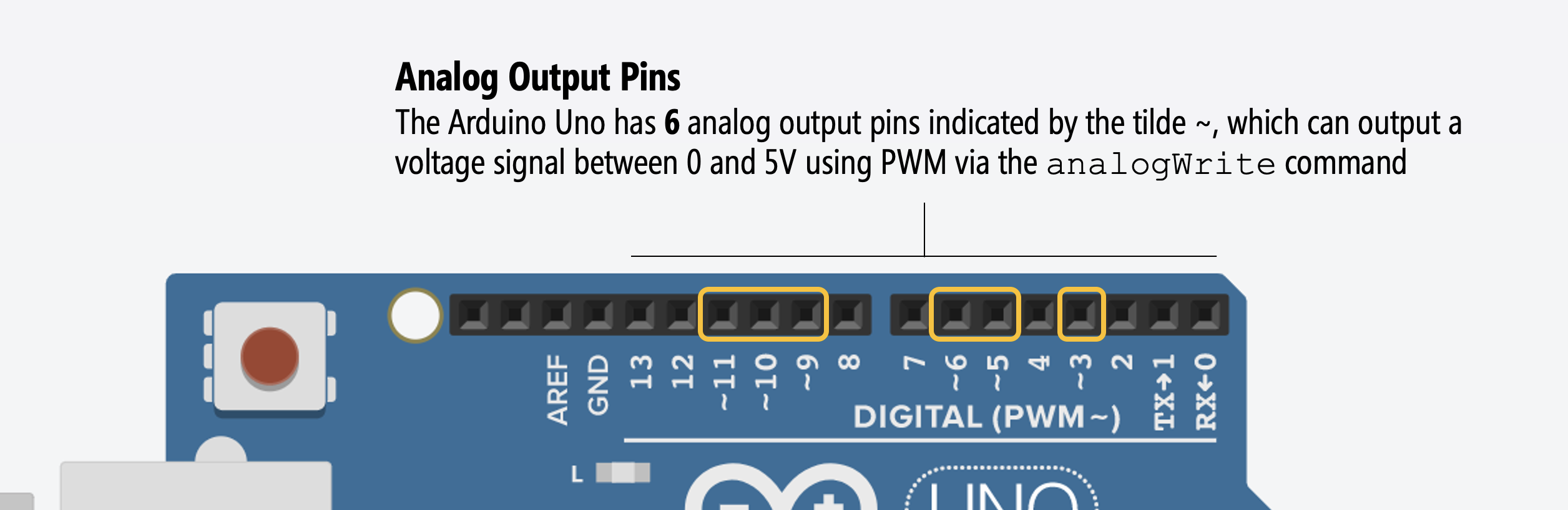
So, for this lesson, we don’t have to change our circuit at all! You can keep the same circuit as the LED blink lesson. Indeed, this is the reason why we selected Pin 3 in the first place.
A common confusion: analog I/O pins are different!
A common confusion amongst beginners is mixing up the analog output pins and the analog input pins. For digital I/O, the input and output pins are the same and configurable to INPUT or OUTPUT using the pinMode command. However, the analog I/O pins are different! See the figure below:
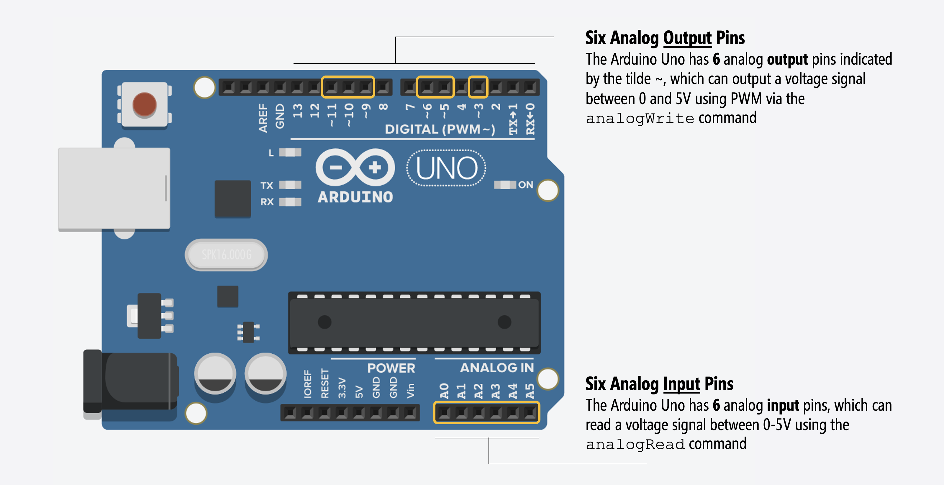
We’ll learn about analog output in this lesson (using analogWrite). In a future lesson, we will learn about analog input (using analogRead).
Using analogWrite
To gradually fade an LED, we are going to use the analogWrite(int pin, int value) function, which takes in a pin as the first parameter and an 8-bit value between 0-255 as the second.
Pulse-width modulation (PWM)
Despite its name, the Arduino Uno, Leonardo, Nano, Mega, and many other Arduino boards do not actually provide true analog output via a digital-to-analog converter (DAC). Instead, they use a method called Pulse-Width Modulation (PWM) to emulate analog output. For most purposes—like changing the brightness of an LED or controlling the speed of a motor—this won’t matter; however, if you want to output a high-frequency sinusoidal waveform—a true analog output signal—like playing music, then you’ll need to either find an Arduino microcontroller with a built-in DAC like the Due (see this SimpleAudioPlayer tutorial) or connect your Uno to an external DAC board like this SparkFun MP3 Player Shield.
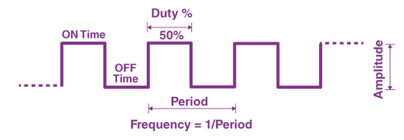
To understand PWM, let’s first remind ourselves of the characteristics of a square waveform: there is the length of time for one full cycle (period), the frequency (how often the cycle occurs per second), the amplitude (a measure from the top to the bottom of the waveform; in this case, 5V), and the duty cycle (the amount of time the waveform is HIGH vs. LOW in a period).
And then take a look at this video by Afrotechmods:
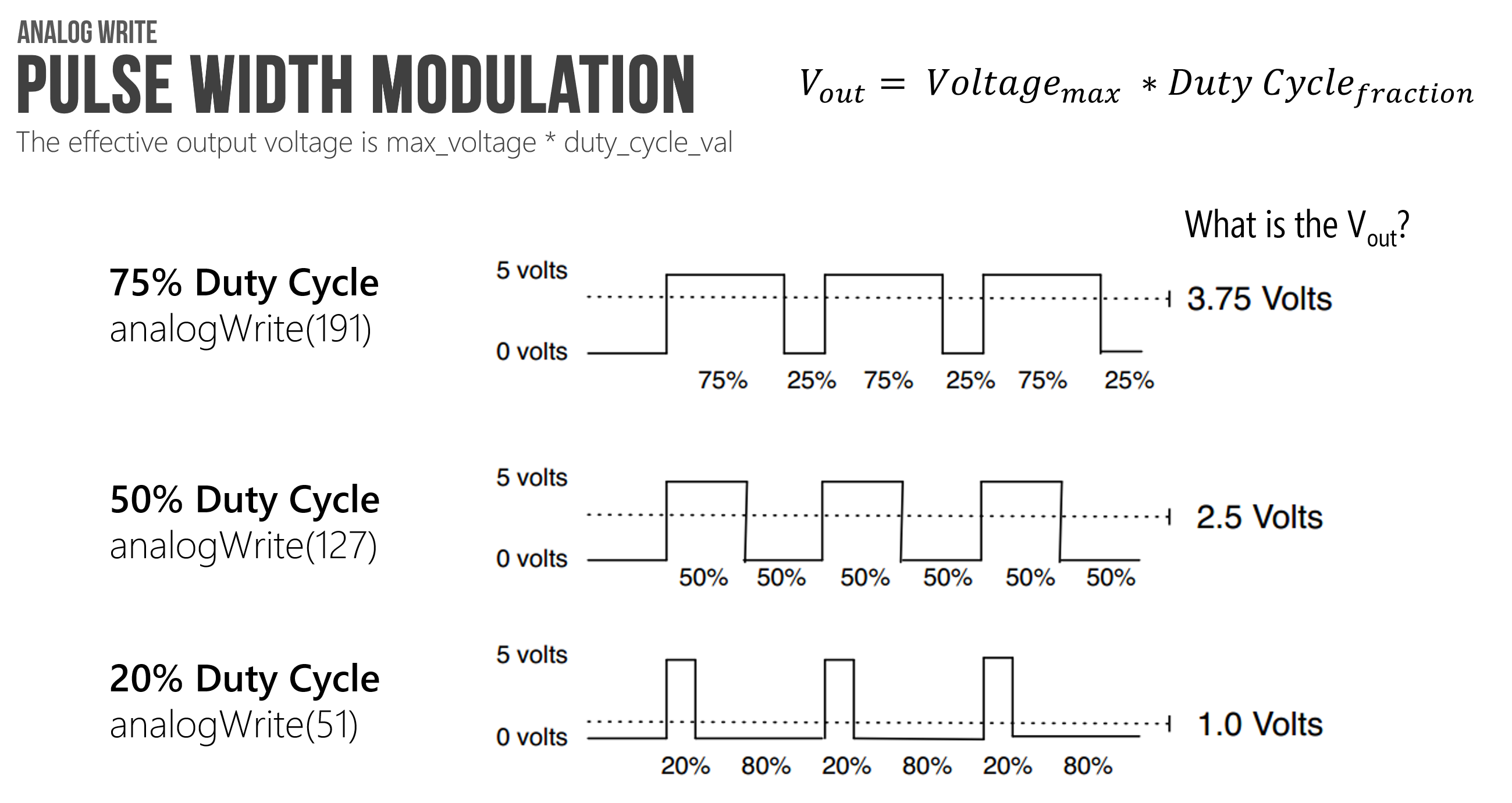
So, what does the analogWrite function do, exactly? It simply varies the duty cycle of the output pin. That is, the 8-bit value (0-255) directly controls how long a 5V value is applied to the output pin during one “analog write” period. So, analogWrite(<pin>, 127) would output a 5V value for half the period (because 127/255 = ~50%) and analogWrite(<pin>, 191) would output a 5V for 75% of the period (because 191/255 = ~75%). This fraction of the time the signal is HIGH is called the duty cycle.
Why does the Uno have only six PWM outputs?
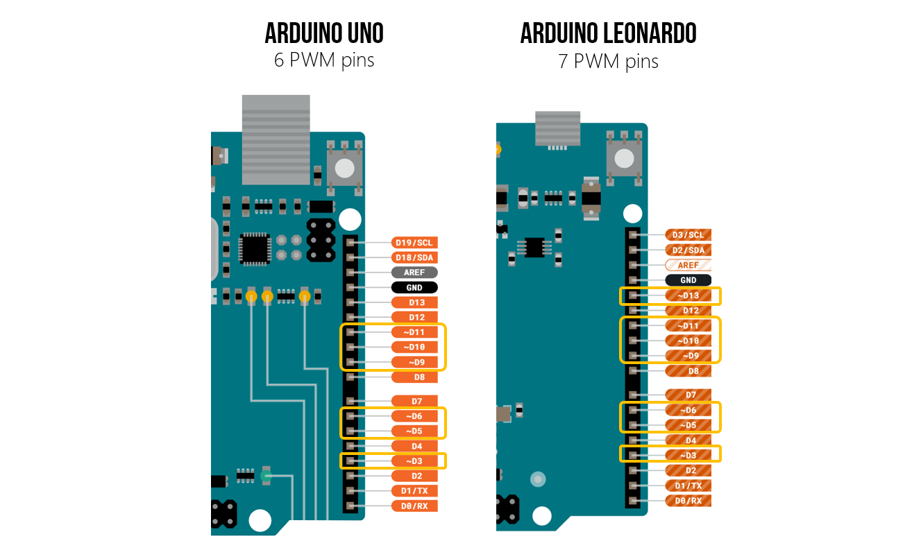
Why does the Arduino Uno only have six PWM outputs? Because the ATmega328 microcontroller has three hardware timers, which control the six PWM outputs.
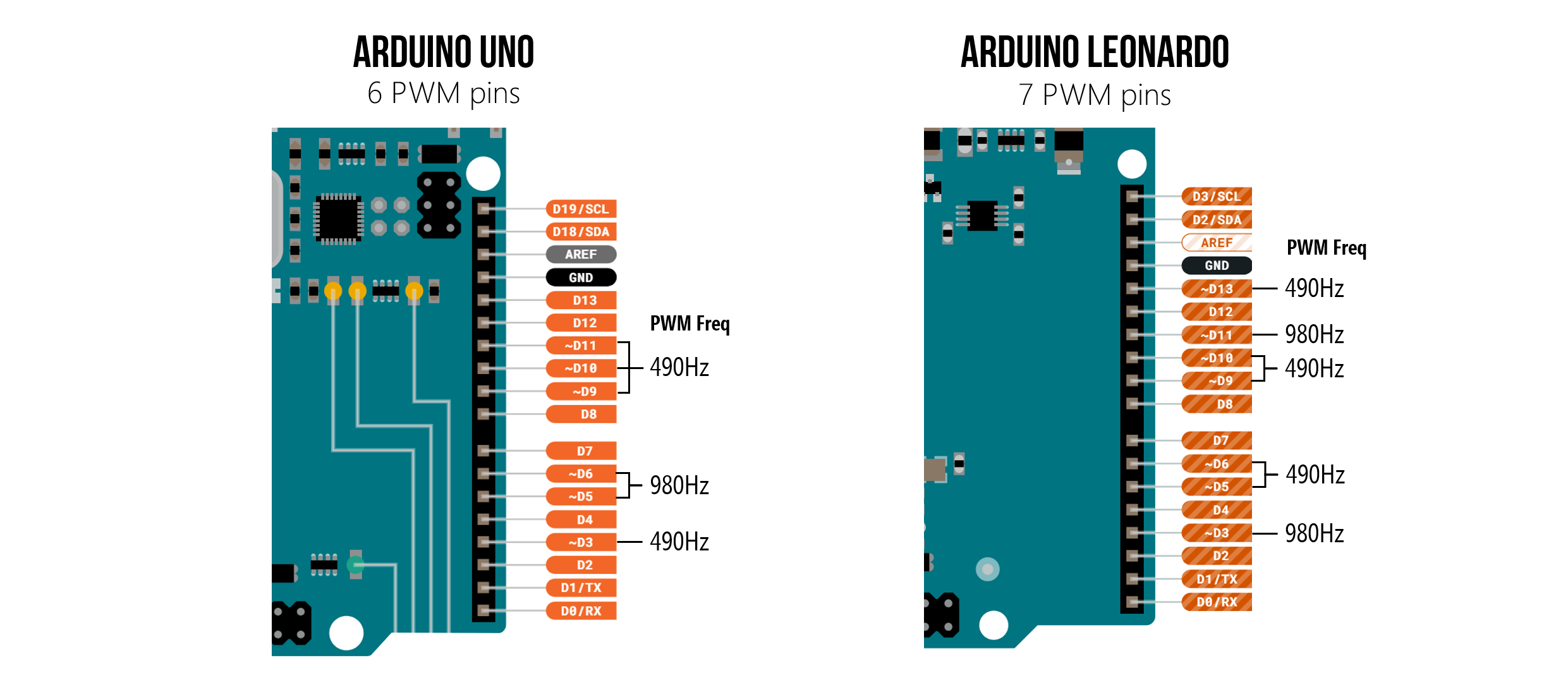
The Arduino Leonardo has seven PWM pins (one more than the Uno) because it has four hardware timers (the new one is called timer4). See the pinout diagrams below.
What is the frequency of the PWM outputs?
On the Uno and Leonardo, PWM outputs are either 490Hz or 980Hz (depending on the underlying hardware timers)—you cannot change the frequency of these waveforms using analogWrite . For the Uno, the PWM pins are 3, 5, 6, 9, 10, 11 (with all pins 490Hz except 5 & 6, which are 980Hz). For the Leonardo, the PWM pins are 3, 5, 6, 9, 10, 11, 13 (all pins 490Hz except 3 & 11, which are 980Hz).
See the image below (and Arduino Docs).
Manually implementing PWM
Could I manually implement PWM on any pin simply by rapidly turning the pin on and off at a desired frequency and duty cycle? Yes, however, the PWM waveform could be jittery (unless you disable interrupts). See: Secrets of Arduino PWM and example code that manually implements a PWM loop.
Learn more about PWM
To learn more about PWM, read this guide from ITP NYU and watch their “analog output” video:
Writing the code
OK, so let’s write some code!
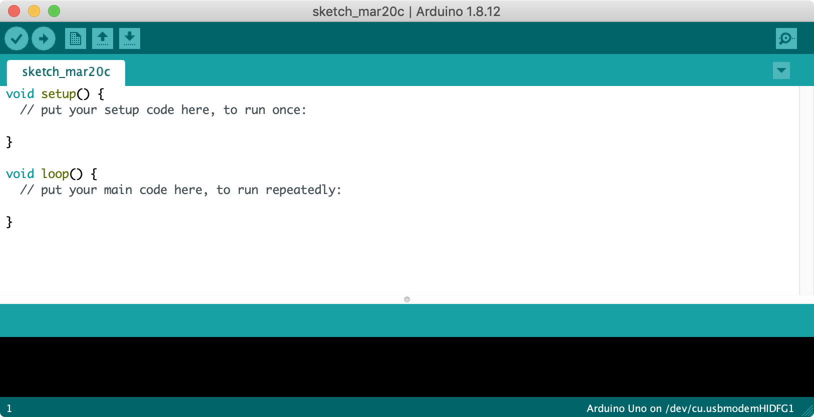
Step 1: Start a new sketch in the Arduino IDE
Start a new sketch in the Arduino IDE:
Step 2: Write initialization code
Our initialization code is the same as for LED blink except for the addition of const int MAX_ANALOG_OUT = 255; and a constant for the delay amount of 5 milliseconds (const int DELAY_MS = 5;).
const int LED_OUTPUT_PIN = 3;
const int MAX_ANALOG_OUT = 255; // the max analog output on the Uno is 255
const int DELAY_MS = 5;

void setup() {
  // set Pin 3 to output
  pinMode(LED_OUTPUT_PIN, OUTPUT);
}
Step 3: Write fade loop
Now, write code that outputs steadily increasing values for analogWrite (to fade on) followed by steadily decreasing values (to fade off).
void loop(){
  // fade on
  for(int i = 0; i <= MAX_ANALOG_OUT; i += 1){
    analogWrite(LED_OUTPUT_PIN, i);
    delay(DELAY_MS);
  }

  // fade off
  for(int i = MAX_ANALOG_OUT; i >= 0; i -= 1){
    analogWrite(LED_OUTPUT_PIN, i);
    delay(DELAY_MS);
  }
}
The full code is embedded below:
This source code is on GitHub.
Step 4: Compile, upload, and run!
Now, compile, upload, and run the code. After upload completes, the LED should immediately begin fading on then off. See video below.
Visualizing the voltage output
What’s actually happening on Pin 3 when we write out different values to analogWrite? Well, remember, basic Arduino boards like the Uno and Leonardo do not have the ability to write out intermediate voltages (they lack digital-to-analog converters or DACs). So, instead, they “fake it” by using pulse-width modulation (PWM) and modulating the fraction of time that a 5V output waveform is HIGH vs. LOW. This is called the duty cycle.
Visualizing the PWM waveform
To let you see how the PWM waveform changes with different analogWrite values on the Arduino Leonardo, we wrote a simple program that takes in an analog input (from a potentiometer, in this case) and uses it to set an analogWrite value to Pin 3. Recall that on the Leonardo, the PWM frequency on Pin 3 is 980Hz (see docs).
Other than the potentiometer, our circuit did not change (we still have an LED with a current-limiting resistor on Pin 3).
Let’s take a look:
To create this program, we had to use both analogRead and analogWrite. By the end of this lesson, you should have a strong understanding of analogWrite and PWM. But we won’t learn more about analogRead until we get to the Introduction to Input microcontroller lessons.
Visualizing the effective voltage output
In addition to visualizing the actual voltage output from analogWrite (the PWM waveform), we can also visualize the (effective) voltage output. For this, we can use Arduino’s Serial Plotter. To access this, open Tools -> Serial Plotter. The plotter will try to visualize any comma separated values you output via Serial.print.
In the video below, we see a simulation of our fade code + circuit running in Tinkercad. On the right side, in the Serial Monitor window, we are printing and graphing out the real-time effective voltages output on Pin 3.
Calculating the current through our LED
Of course, it’s the current through the LED that determines brightness. But how can we calculate (effective) current with PWM?
Again, given Ohm’s Law (\(I = \frac{V}{R}\)), we can determine the current through our circuit at various Pin 3 outputs. Recall that current does not pass through an LED until its forward voltage \(V_f\) condition is met. With a red LED, a common forward voltage is \(V_f=2V\). With analogWrite, the GPIO pin is still driven HIGH (5V) but only for a fraction of the time due to PWM (this fraction is called the duty cycle). So, the \(V_f\) requirement is still met and our eyes perceive the LED on but it’s actually flashing on/off imperceptibly quickly!
To calculate the current through our LED circuit with PWM, let’s let \(DF\) equal the duty cycle fraction, the fraction of a waveform period that is HIGH. Then, we can use the following equation: \(I = \frac{V_s - V_f}{R} * DF\) to calculate current. So, for example, if we analogWrite a 51 then our \(DF=\frac{51}{255}=0.2\). With a 220Ω, our current would be: \(I=\frac{5V - 2V}{220Ω}*0.2=2.7mA\).
See the table below for example 8-bit output values for analogWrite on Pin 3 and the effective current.
| Resistor | Pin 3 Voltage | Pin 3 Value | PWM Duty Cycle | Resulting Current |
|---|---|---|---|---|
| 220Ω | 5V | 0 | \(\frac{0}{255}=0.0\) | \(I = \frac{5V-2V}{220Ω} * 0.0=0.0mA\) |
| 220Ω | 5V | 45 | \(\frac{45}{255}=0.176\) | \(I = \frac{5V-2V}{220Ω} * 0.176=2.4mA\) |
| 220Ω | 5V | 103 | \(\frac{103}{255}=0.404\) | \(I = \frac{5V-2V}{220Ω} * 0.404=5.5mA\) |
| 220Ω | 5V | 128 | \(\frac{128}{255}=0.502\) | \(I = \frac{5V-2V}{220Ω} * 0.502=6.8mA\) |
| 220Ω | 5V | 199 | \(\frac{199}{255}=0.780\) | \(I = \frac{5V-2V}{220Ω} * 0.780=10.5mA\) |
| 220Ω | 5V | 255 | \(\frac{255}{255}=1.0\) | \(I = \frac{5V-2V}{220Ω} * 1.0=13.4mA\) |
Improved fading approach: removing for loop
Remember in the LED blink lesson where we mentioned wanting to avoid long for loops and long delays in our code. Why? Because while we are in a delay, we can’t do anything else: we can’t read or respond to other input (side note: we could use interrupts but let’s defer that point for now). See “What does delay() actually do?” in our Inside Arduino guide.
So, let’s rewrite the fade example but without for loops and, instead, rely on the fact that loop() is already a loop :). While the code below is different, the resulting LED fade behavior is the same (so you won’t notice a difference if you try them both out).
I have a habit of prefixing my global variables by
_but this is just my own convention and helps me easily discern between local variables and global variables. You need not do this, of course! 😊
const int LED_OUTPUT_PIN = 3;
const int MAX_ANALOG_OUT = 255; // the max analog output on the Uno is 255
const int DELAY_MS = 5;

int _fadeAmount = 5;      // the amount to fade the LED by on each step
int _curBrightness = 0;   // how bright the LED is

// The setup function runs once when you press reset or power the board
void setup() {
  // set the LED pin to as an output
  pinMode(LED_OUTPUT_PIN, OUTPUT);
  Serial.begin(9600); // for using Serial.println
}

// The loop function runs over and over again forever
void loop() {

  // set the brightness of the LED pin
  analogWrite(LED_OUTPUT_PIN, _curBrightness);

  // change the brightness for next time through the loop
  _curBrightness = _curBrightness + _fadeAmount;

  // reverse the direction of the fading at the end of each fade direction
  if (_curBrightness <= 0 || _curBrightness >= MAX_ANALOG_OUT) {
    _fadeAmount = -_fadeAmount; // reverses fade direction
  }

  // wait for some milliseconds to see the dimming effect
  delay(DELAY_MS);
}
You can find this code in GitHub.
Exercises
Want to go further? Here are some design challenges to reinforce what you’ve learned:
- Eliminate delays entirely. Can you rewrite the fade code without using
delay()at all, using themillis()-based approach from Blink without delay? Try it yourself, then compare with our solution. - Different fade step sizes. Try changing
_fadeAmountto1,10, or25. How does the step size affect the smoothness of the fade? What about the fade speed? - Non-PWM pin. What happens if you use
analogWriteon a pin that doesn’t support PWM (e.g., Pin 4)? Try it and observe the result. - Graph it. Use the Serial Plotter to graph the
_curBrightnessvalue over time. Does the graph match what you’d expect?
Lesson Summary
In this lesson, you unlocked the ability to create intermediate voltage levels using code! You learned:
- How to use
analogWrite()to output an 8-bit value (0-255). - What Pulse-Width Modulation (PWM) is, and how it emulates analog output by varying the duty cycle of a square wave.
- Why LEDs appear to dim when driven by a PWM signal (our eyes average out the high-speed flashing).
- How to calculate the effective current through an LED when using PWM.
- How to write a non-blocking fade loop by stepping a variable rather than using long
forloops.
Next Lesson
In the next lesson, we’ll learn how to play sounds on a piezo buzzer!