Lesson 9: Rate Blinking LEDs
Table of Contents
In this lesson, we will learn how to blink multiple LEDs at different rates and build our first C/C++ class, which will greatly simplify our code and, as an added bonus, reduce its size by eliminating code redundancy!
As with our previous lesson on crossfading RGB LEDs, this lesson involves simple circuits but comparatively complex code. Often, when using microcontrollers, our code is the magic sauce—the circuits are straightforward but the code can be complicated.
Background
The canonical and beloved first Arduino sketch, Blink, enables beginners to quickly build and write code for a circuit. The code looks something like this, which we covered in our own Blink lesson:
void setup() {
  // set Pin 3 to output
  pinMode(3, OUTPUT);
}

void loop() {
  digitalWrite(3, HIGH);  // turn LED on (output 5V)
  delay(1000);            // wait one second
  digitalWrite(3, LOW);   // turn LED off (output 0V)
  delay(1000);            // wait another second
}
Blink is easy. It’s gratifying. But… it sets up a flawed mental model about how to structure programs and when/how to use delay().
What if you want to blink multiple LEDs at different rates? How would you do this with delay()? Well, you can’t. While in a delay(), your program is literally doing nothing (well, it’s stuck in a while loop waiting for the delay period to finish but that’s essentially nothing).
So, what should we do instead? We eliminate all delays and track time and state using state machines. Alternatively, we could use interrupts (but we’ll cover that later).
Materials
You’ll need three LEDs—we’ll use red, blue, and yellow but you can use whatever LEDs you want—along with current limiting resistors, a breadboard, and an Arduino.
| Breadboard | Arduino | Three LEDs | Three Resistors |
|---|---|---|---|
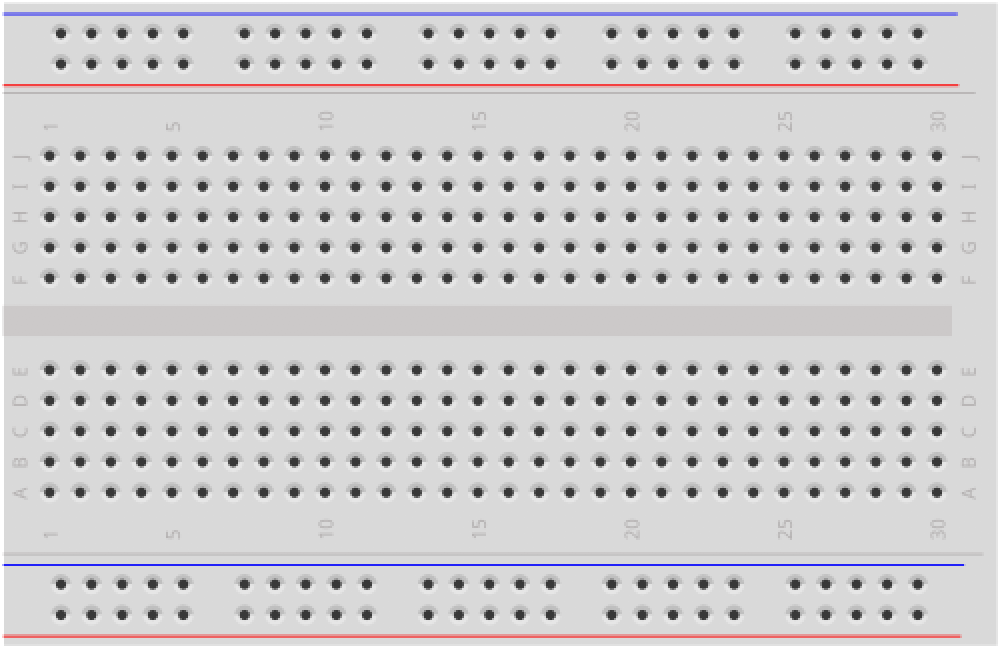 | 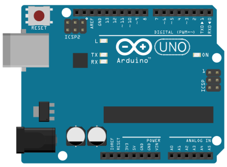 | 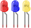 |  |
| Breadboard | Arduino Uno, Leonardo, or similar | Three LEDs (We’ll use a red, blue, and yellow) | Three 220Ω Resistors |
Circuit
The circuit is the same as our basic LED blink lesson but we duplicate it three times—once for each LED. We could use any of the Arduino’s GPIO pins, but we chose Pins 2, 5, and 9 simply to space out the circuit and make it easier to read.
By now, this circuit and wiring should feel familiar. Indeed, you may not even need a wiring diagram like this to help!
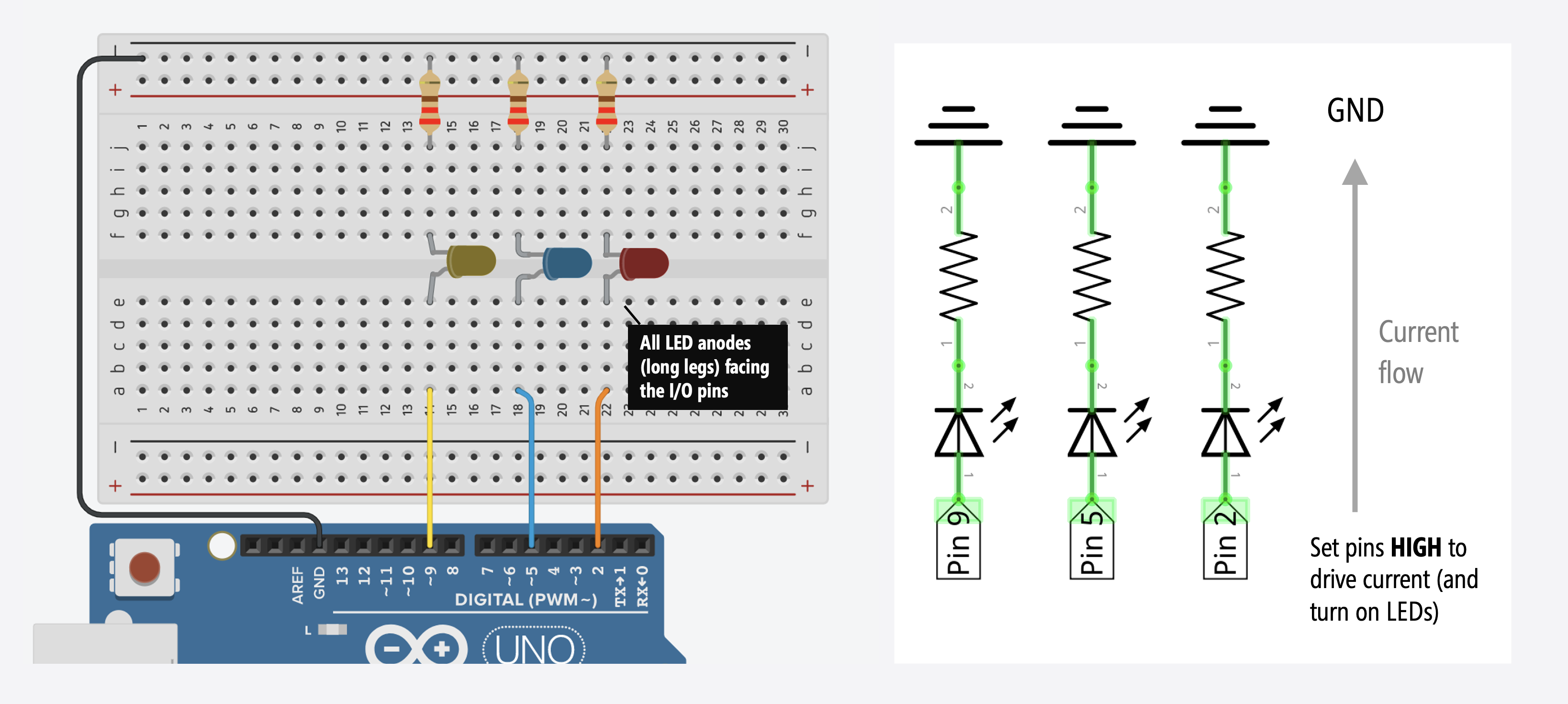
Recall that each LED color has a unique forward voltage Vf. In this case, our red LED has a Vf between 2.0-2.4V, our blue LED between 3.0-3.4V, and our yellow LED between 2.0-2.4V. To simplify things, we’ll use the same value resistor for each LED circuit (220Ω); however, you could use different resistors for each LED to try and balance brightness levels.
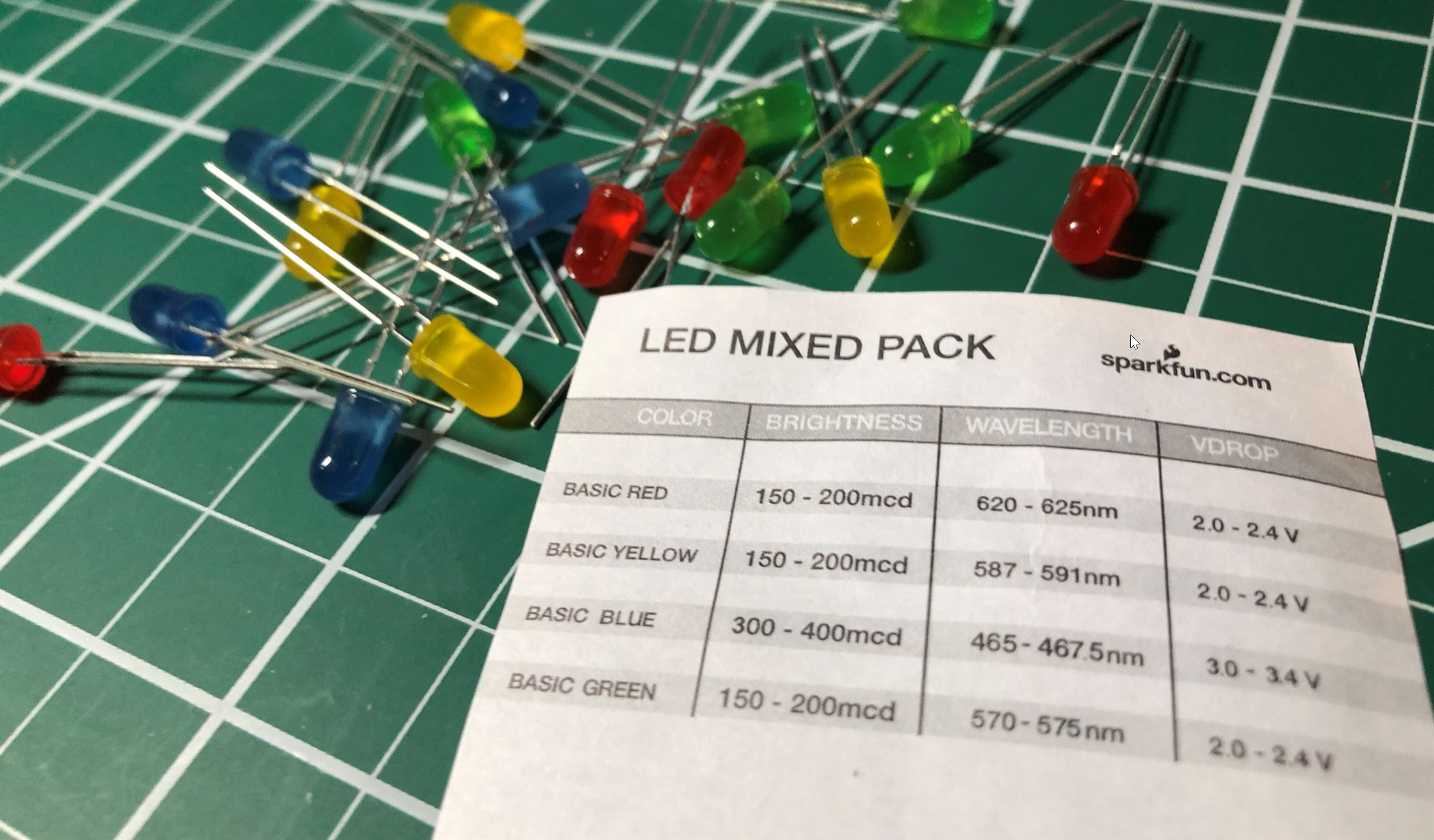 The LED assorted pack from Sparkfun.com, which shows the Vdrop (or Vf) for each LED.
Writing code
We are going to implement two multi-rate blinking approaches:
- The first introduces the overall idea of using state tracking variables and state change timestamps to control timing output without
delays(). - The second will use the same approach but simplified using object-oriented programming. Here, we’ll also show you how to make and use a
C++class in Arduino.
Multi-rate blinking: an initial approach
For our initial approach, we need four things for each LED:
- Pin number: An integer value specifying the output pin.
- Blink interval: A per-LED interval that controls how long to turn on (
HIGH) and off (LOW) the LED. - Toggle timestamp: The last time the LED was toggled from
HIGHtoLOWorLOWtoHIGH. - Current LED state: The current LED state (either
HIGHorLOW), which is toggled every blink interval.
Blink interval
For the blink interval, we’ll use const variables like LED1_BLINK_INTERVAL_MS, LED2_BLINK_INTERVAL_MS, and LED3_BLINK_INTERVAL_MS
const int LED1_OUTPUT_PIN = 2;
const int LED1_BLINK_INTERVAL_MS = 200; // interval at which to blink LED1 (in milliseconds)

const int LED2_OUTPUT_PIN = 5;
const int LED2_BLINK_INTERVAL_MS = 333; // interval at which to blink LED2 (in milliseconds)

const int LED3_OUTPUT_PIN = 9;
const int LED3_BLINK_INTERVAL_MS = 1111; // interval at which to blink LED3 (in milliseconds)
Toggle timestamps and LED states
For the toggle timestamps and LED states, we’ll use variables like _led1LastToggledTimestampMs and _led1State. We can toggle ledState simply by: ledState = !ledState.
unsigned long _led1LastToggledTimestampMs = 0; // tracks the last time LED1 was updated
int _led1State = LOW; // will toggle between LOW and HIGH

unsigned long _led2LastToggledTimestampMs = 0; // tracks the last time LED2 was updated
int _led2State = LOW; // will toggle between LOW and HIGH

unsigned long _led3LastToggledTimestampMs = 0; // tracks the last time LED3 was updated
int _led3State = LOW; // will toggle between LOW and HIGH
To capture timestamps, we’ll use Arduino’s millis() function, which returns “the number of milliseconds passed since the Arduino board began running the current program” as an unsigned long.
On the Arduino, the unsigned long data type is 32 bits (4 bytes), which ranges from 0 to 4,294,967,295 (2^32 - 1). Thus, millis() will overflow—go back to zero and begin again—after 4,294,967,295 milliseconds (or approximately 50 days). If you need more precise timing, you could use micros(), which provides microsecond resolution rather than millisecond resolution but micros() overflows every ~70 minutes.
Blinking without delays logic
We then use the same general logic as the “blinking without delays” covered previously for each LED:
unsigned long currentTimestampMs = millis();

// Check to see if we reached the toggle state interval for LED1
if (currentTimestampMs - _led1LastToggledTimestampMs >= LED1_BLINK_INTERVAL_MS) {
  _led1LastToggledTimestampMs = millis();
  _led1State = !_led1State;
  digitalWrite(LED1_OUTPUT_PIN, _led1State);
}

// Check to see if we reached the toggle state interval for LED2
if (currentTimestampMs - _led2LastToggledTimestampMs >= LED2_BLINK_INTERVAL_MS) {
  _led2LastToggledTimestampMs = millis();
  _led2State = !_led2State;
  digitalWrite(LED2_OUTPUT_PIN, _led2State);
}

... // and so on, copy the above block of code for each LED you're trying to blink
Tracking timestamps and overflow
This sub-section provides more background on tracking timestamps and overflow. Feel free to skip this if you’d like.
An important question to ask is: what happens if my Arduino needs to run for more than ~50 days and I’m relying on millis() to track time? Will the subtraction math (currentTimestampMs - _lastToggledTimestampMs >= LED_BLINK_INTERVAL_MS) still work? Even during an overflow condition?
Great question! And yes, it will still work! And the reason is because we are using unsigned data types, which inform the compiler that these values can never be < 0. This is crucial.
For example, imagine that _lastToggledTimestampMs is 4,294,967,290 or 0xFFFFFFFA in hexadecimal (32 bits), which is 5 milliseconds from overflow. And then imagine that millis() overflows (returns back to 0) and currentTimestampMs becomes, say, 1 or 0x00000001. So, our subtraction is then: 0x00000001 - 0xFFFFFFFA. There is 7 milliseconds difference between these two numbers, so we’d like the subtraction to result in 7:
1. 0xFFFFFFFA
2. 0xFFFFFFFB
3. 0xFFFFFFFC
4. 0xFFFFFFFD
5. 0xFFFFFFFE
-. (0xFFFFFFFF) <-- overflow
6. 0x00000000
7. 0x00000001
And this is what we get! Feel free to experiment with this yourself by running the code below on you Arduino. We also suggest this article by James Lewis about millis(), overflow, and arithmetic for more background.
unsigned long _lastToggledTimestampMs = 4294967290; // change this to experiment with overflow

void setup() {
  Serial.begin(9600);
  delay(2000);
}

void loop() {

  unsigned long currentTimestampMs = 1;
  unsigned long diff = currentTimestampMs - _lastToggledTimestampMs;

  Serial.println("The subtraction between: currentTimestampMs - lastToggledTimestampMs is: ");
  Serial.print(currentTimestampMs);
  Serial.print(" - ");
  Serial.print(_lastToggledTimestampMs);
  Serial.print(" = ");
  Serial.println(diff);
  delay(1000);

  _lastToggledTimestampMs++;
}
The full code for multi-rate blinking
OK, now back to the code. So, our full code for multi-rate blinking is below:
This source code is on GitHub.
Workbench video
Multi-rate blinking: an object-oriented approach
Given the amount of code redundancy and shared logic and structure, the above solution is a strong candidate for refactoring into functions or classes. So, let’s do it!
We’re going to define a new class, called Blinker, which will greatly simplify our code, decrease redundancy (and the potential for human error), and even make our compiled code smaller (from 1,118 to 1,042 bytes of program storage space).
Once we’ve made the Blinker class, our main code reduces to:
Blinker _led1Blinker(2, 200);  // specify pin and blink interval (200ms)
Blinker _led2Blinker(5, 333);  // specify pin and blink interval (333ms)
Blinker _led3Blinker(9, 1111); // specify pin and blink interval (1111ms)

// The setup function runs once when you press reset or power the board
void setup() {
  // empty
}

// The loop function runs over and over again forever
void loop() {
  _led1Blinker.update();
  _led2Blinker.update();
  _led3Blinker.update();
}
But we have to make the Blinker class first, which we do below!
Making the Blinker class
If you’re familiar with object-oriented programming and declaring and using classes in Java, C#, Python, and even, to some extent, JavaScript since ECMAScript 2015, then C++ classes will feel familiar (but certainly have their own peculiarities). C++ classes have a class name, member variables, member functions, and like C# and Java, access specifiers (e.g., private, public). For a quick tutorial, see these links (link1, link2).
To build our Blinker class, recall that we need four things per LED:
- Pin Number: An integer value specifying the output pin.
- Blink Interval: A blink interval that controls how long to turn on (
HIGH) and off (LOW) each LED. - Toggle Timestamp: The last time the LED was toggled from
HIGHtoLOWorLOWtoHIGH. - Current LED State: The current LED state (either
HIGHorLOW), which is toggled every blink interval.
For the Blinker class, we are simply going to convert these four things into member variables:
class Blinker{

  private:
    const int _pin;                 // output pin
    const unsigned long _interval;  // blink interval in ms

    int _state;                     // current state (either HIGH OR LOW)
    unsigned long _lastToggledTimestamp; // last state toggle in ms

  ... // more here
Finally, we need two functions: a constructor and update()—the latter which handles our core logic and toggling code and is intended to be called once per loop() iteration. We are going to declare these in the class definition itself:
  public:
    // Constructor
    Blinker(int pin, unsigned long blinkInterval) :
        _pin(pin), _interval(blinkInterval) // initialize const like this in C++
    {
      _state = LOW;
      _lastToggledTimestamp = 0;
      pinMode(_pin, OUTPUT);
    }

    /**
    * Calculates whether to toggle output state based on the set interval
    * Call this function once per loop()
    */
    void update(){
      unsigned long currentTimestampMs = millis();

      if (currentTimestampMs - _lastToggledTimestamp >= _interval) {
        _lastToggledTimestamp = currentTimestampMs;
        _state = !_state;
        digitalWrite(_pin, _state);
      }
    }
In order to use the Blinker class (as shown above), it needs to be defined within your .ino sketch at the top of the file (before you try to instantiate a Blinker object). Later, we’ll also show how to create a class that exists in its own .h and .cpp files.
Full Blinker code
So, the entire code looks like this:
This source code is on GitHub.
Multi-rate blinking: using an external class
In C++, you declare member variables and function signatures in a .h file and the function implementations in a .cpp file. This is often a cleaner solution than embedding classes within the .ino itself.
Indeed, if we move Blinker into separate .h and .cpp files, then the full .ino sketch simply looks like:
See the code in our GitHub repository.
Workbench video
Exercises
Want to go further? Here are some design challenges to help improve your skills:
- Dynamically changing intervals. What if we wanted to support dynamically changing blink intervals—that is, once the Blinker object was instantiated. How would you do this?
- Morse code. Try adapting the Blinker class to support a sequence of on and off intervals like Morse code
- Fade. What about fading the LEDs rather than flashing them. How would you do this? Stuck? Nick Gammon wrote a class for this on his blog called LedFader but don’t look at his solution until you’ve tried your own!
References
Some additional references:
- Multi-tasking the Arduino: Part 1 - Blinking without delays, Adafruit Learn
- Multi-tasking the Arduino: Part 2 - Using interrupts, Adafruit Learn
- Multi-tasking the Arduino: Part 3, Adafruit Learn
- How to do multiple things at once, Nick Gammon
Lesson Summary
Congratulations! You’ve graduated from basic blinking to state-machine-driven, object-oriented programming. In this lesson, you learned:
- Why using
delay()prevents an Arduino from performing multiple timing tasks simultaneously. - How to use
millis()to track time and trigger events asynchronously. - How integer overflow works with
unsigned longdata types, ensuringmillis()math remains accurate even after 50 days of uptime. - How to encapsulate timing logic into a reusable
C++class (Blinker) to drastically reduce code redundancy. - How to separate
C++classes into external.hand.cppfiles.
Next Lesson
We did it! This completes our Intro to Output series. Let’s now begin Intro to Input to learn about buttons, sensors, voltage dividers, and more!