Lesson 2: Circuit Schematics
Table of Contents
- Common electronic symbols
- Pictorial vs. circuit schematics
- Schematics do not capture physical arrangement
- Representing connected vs. unconnected wires
- Voltage source and ground nodes
- Schematic building tools
- Activity: Building circuit diagrams in Fritzing
- Resources
- Next Lesson
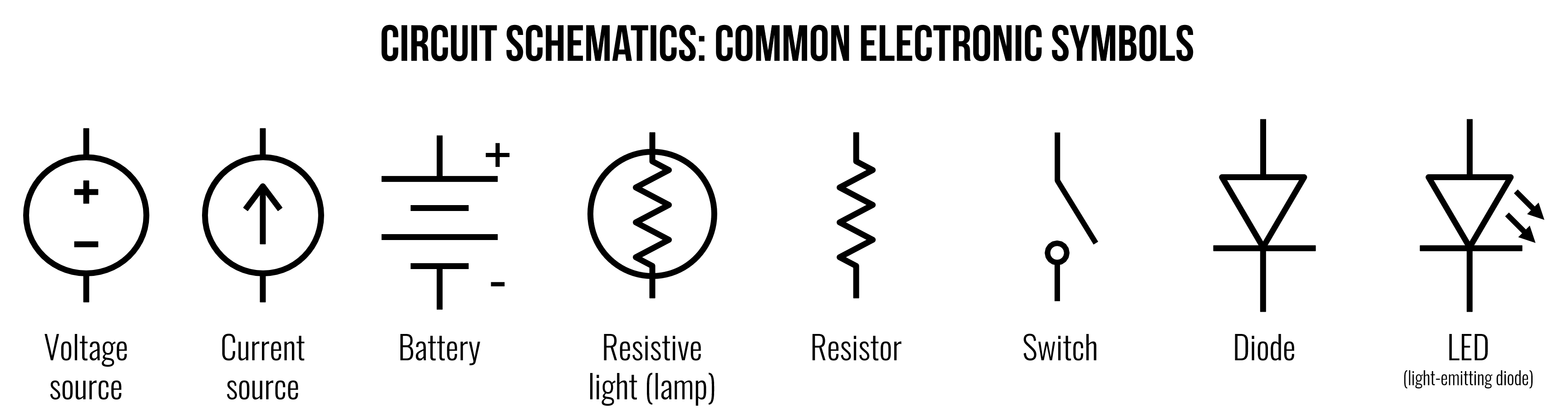 Figure. A preview of what we’ll build: by the end of this lesson, you’ll be able to read and draw circuit schematics using standardized component symbols like these—the visual language of electronics.
Before going any further, it’s useful to introduce circuit schematics, which are diagrammatic abstractions of circuits—this will allow us to “speak” about and describe circuits visually.
Unlike the more realistic pictorials that we have used thus far (e.g., like this or this), circuit schematics are the lingua franca of electronics—they are compact, standardized, visual representations of circuits. You’ll find them in electronic datasheets, CAD layout software, and circuit analysis.
But, like any “language”, schematics take time and experience to learn and understand. For the most part, we will try to offer both pictorial representations and schematic representations in our tutorials but schematics are preferred for circuit analysis and you’ll need to build up understanding in order to parse component datasheets—an important skill!
Common electronic symbols
Below, we’ve included some common electronic symbols for basic circuits. We will begin using these symbols in our next lesson on Ohm’s Law, so it’s important to study them. What do you observe?
For the most part, the symbols are clean, distinguishable, and help capture the “essence” of the underlying component. Notice how a resistor and a resistive (incandescent) lamp are related—and, as resistive elements, they share a zig-zaggy line. Notice too how the diode and light-emitting diode (LED) are visually similar (they are both diodes!)—the latter includes two little arrows indicating light emission.
For more examples, see Wikipedia’s entry or visit one of the Resources listed below.
Figure. Common electronic symbols. For the battery, the long line is used to indicate the positive terminal and the short line is the negative terminal (which is typically used as ground). Image made in PowerPoint.
We have not included the ground (GND) symbol in the chart above, but it is one of the most important symbols you’ll encounter. We cover it later in Voltage Sources and Ground Nodes.
Pictorial vs. circuit schematics
To demonstrate the difference and utility of pictorial vs. circuit schematics, we provide some examples below.
In the first example, we have a 1.5V battery with a 100Ω resistor. Unlike pictorial diagrams (on the left), circuit diagrams can be more visually compact as well as legible in black-and-white.
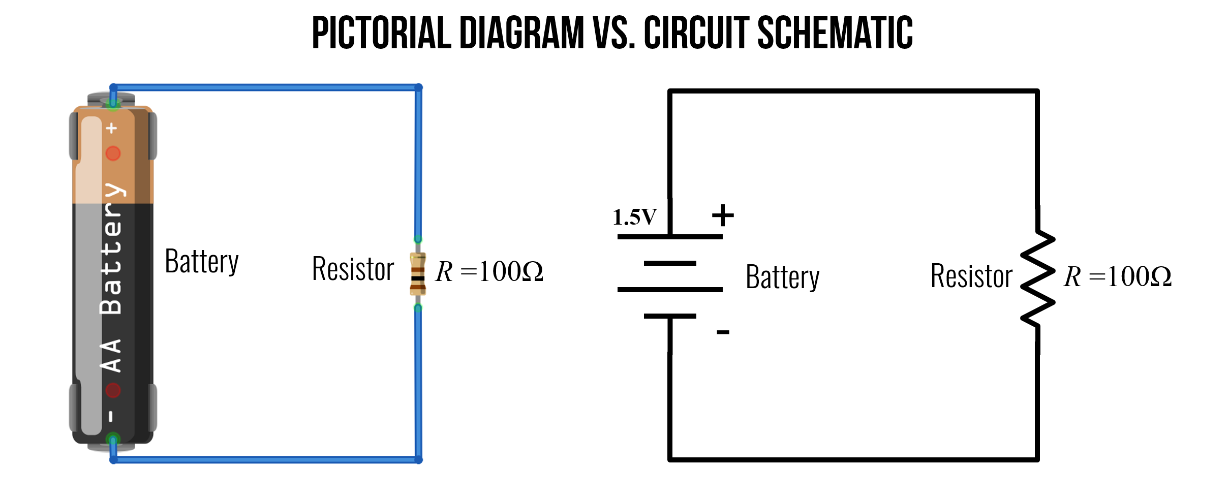
Figure. An example pictorial diagram and circuit schematic of a basic circuit with a 1.5V battery and a resistor. Note: in a circuit schematic, the long line on the battery is used to indicate the positive terminal. Image made in Fritzing and PowerPoint.
Below, we have two additional examples. On the left, a 9V circuit with three components: a switch, a 470Ω resistor, and an LED. On the right, we have two 1.5V batteries in series (stacked together, which creates a 3V voltage source) and a resistive light bulb (lamp). Do the schematic representations make sense? Do they seem to match their pictorial counterparts? Why or why not?
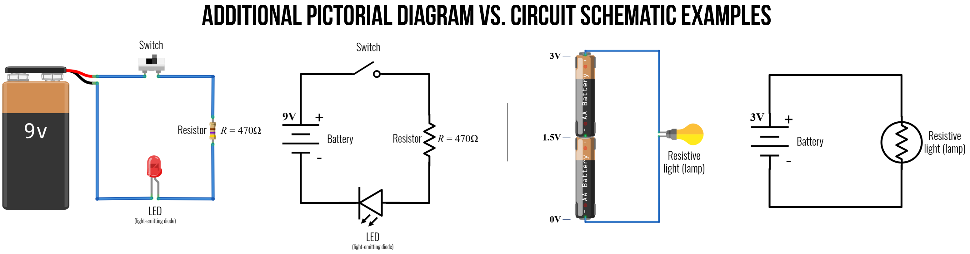
Figure. Additional examples of pictorial diagrams vs. circuit schematics for two more circuits. Right-click on the image and open it in a “new tab” to zoom. Image made in Fritzing and PowerPoint.
Schematics do not capture physical arrangement
A circuit schematic captures the relative ordering of and connections between components, but the spacing and physical layout are not represented. You can use a circuit schematic to build a circuit—a bit like following Ikea instructions—but the schematic only specifies the electrical relationships between components. So, you can use whatever spatial layout you want, as long as it is functionally equivalent to the diagram.
For example, the following five schematics of a basic LED circuit are all functionally equivalent! Take your time reading them—do you agree that they are all equivalent? What stands out to you?
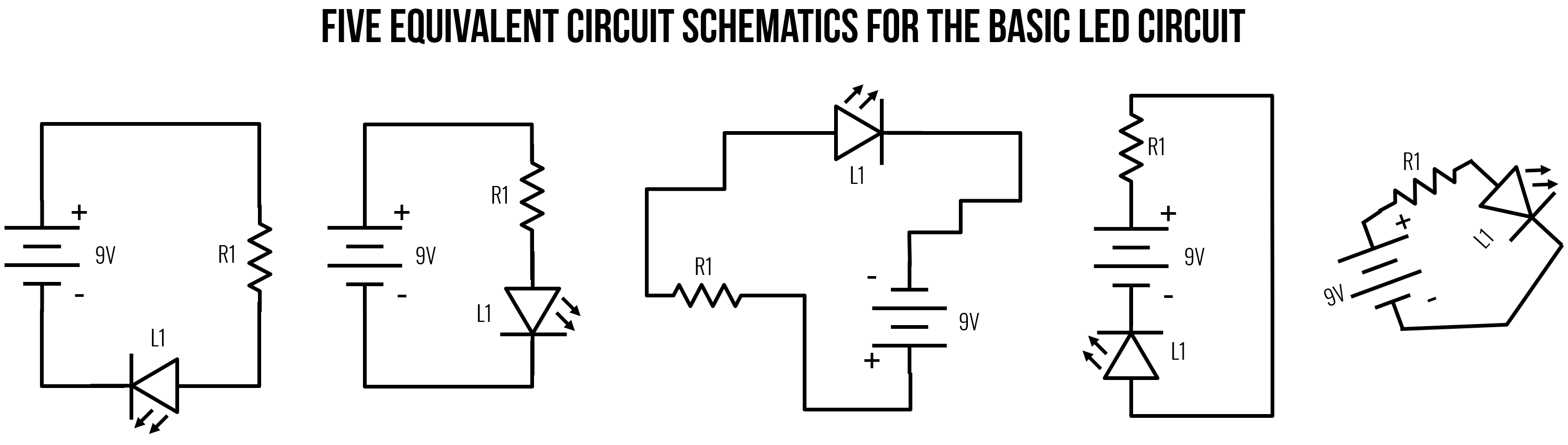
Figure. Though they look different, all five of these basic LED circuits are functionally equivalent. Each of them have the positive terminal of the battery connected to a resistor, then an LED, and the cathode of the LED is connected to the negative terminal of the battery. Image made in PowerPoint.
Representing connected vs. unconnected wires
When reading a circuit schematic, it can be difficult to properly interpret crossing wires—i.e., “are those wires connected or not?” Thankfully, there is a standard for this as well (though some deviations are possible).
A wire is shown as a solid line. When two or more wires connect, the junction is typically depicted by a black dot—we call this junction a node.
For crossing (unconnected) wires, there is no black dot. As Hughes notes, schematics created before ~1980 used a hump or arc to indicate that one wire crossed another without connecting (far right in image below). While valuable, this practice is far less common today perhaps because of the greater complexity of modern circuits, which have more crossing wires (thus, those humps could be visually distracting).
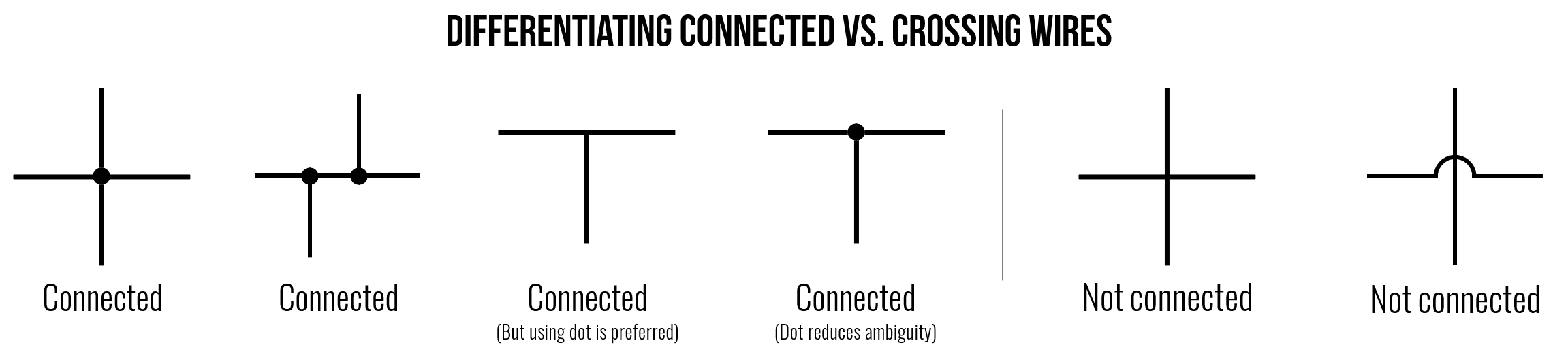
Figure. When reading a circuit schematic, it’s important to properly assess and understand which wires are connected and how—but determining whether a crossing wire is unconnected (e.g., jumping over a wire) or connected (i.e., forming a node) can be confusing. Above, we show various examples of how to interpret whether wires are connected in a circuit diagram. Image made in PowerPoint.
But this can quickly get confusing. For example, are the two circuits below equivalent or not? In fact, they are! When in doubt, redraw the circuit yourself on a piece of paper!
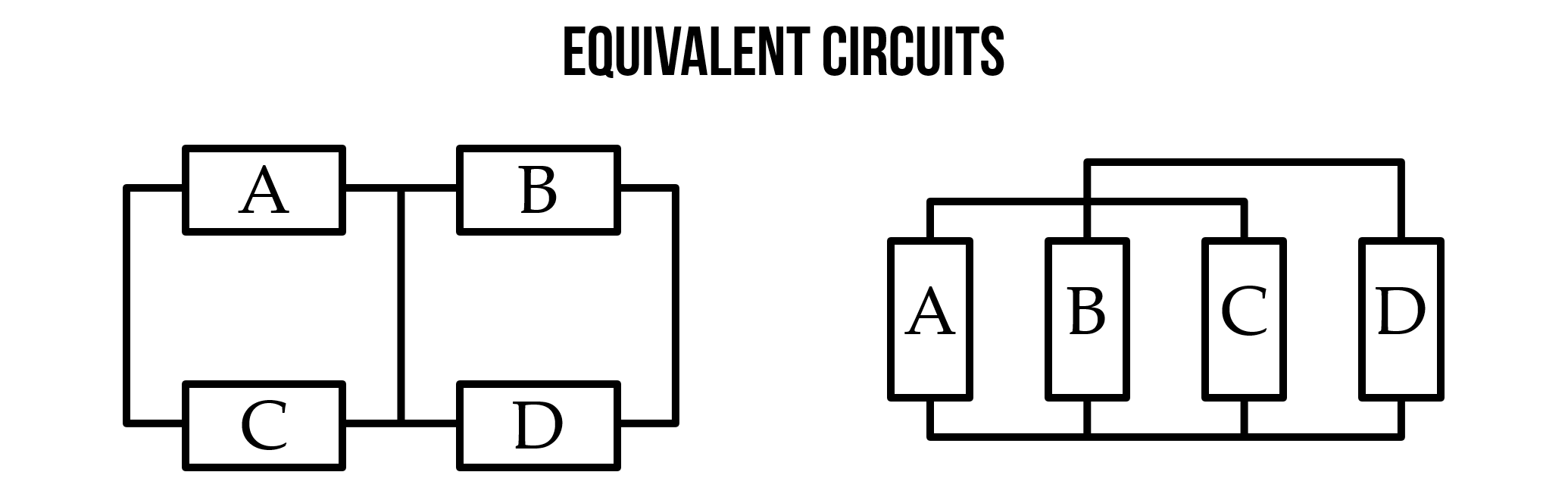
Figure. An example of how even simple circuits can start to get confusing. What’s connected to what? Are these two circuits the same? In fact, yes! When in doubt, redraw the circuit on paper. Image from Stanford’s ENGR 40M course.
Voltage source and ground nodes
On many circuit diagrams, you’ll see special symbols used to denote the voltage source and ground nodes. As introduced in Lesson 1, ground (GND) is the reference point we define as 0V. Positive voltage source nodes are usually indicated by an upward-pointing arrow labeled with a voltage value (e.g., “5V” or “\(V_{CC}\)”). Ground nodes are typically pointed downward and come in several visual styles: a single flat horizontal line, a downward-pointing triangle, or three progressively shorter horizontal lines stacked vertically.

Figure. Using these symbols has the advantage of more clearly marking what the reference or ground node of a circuit is but, more importantly, also allows the circuit designer to render more clean diagrams (by removing needless wires).
For example, all four versions of this simple LED-based circuit are functionally equivalent but the one on the right is far simpler.
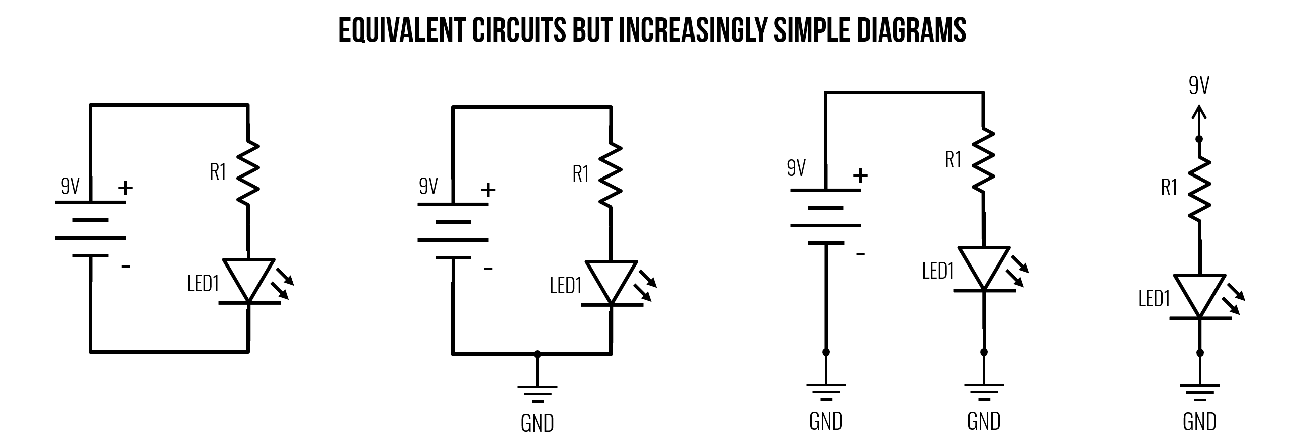
Figure. Four examples of the same circuit drawn differently. The circuit visuals become increasingly minimalist from left-to-right. Image made in PowerPoint (inspired by Section 5.6 of Electronics for Beginners).
A real example
In the schematic below, you can see how the circuit designer made use of the voltage source and ground node symbols. This declutters the diagram by reducing the need to have many lines (wires) drawn to a shared \(GND\) node.
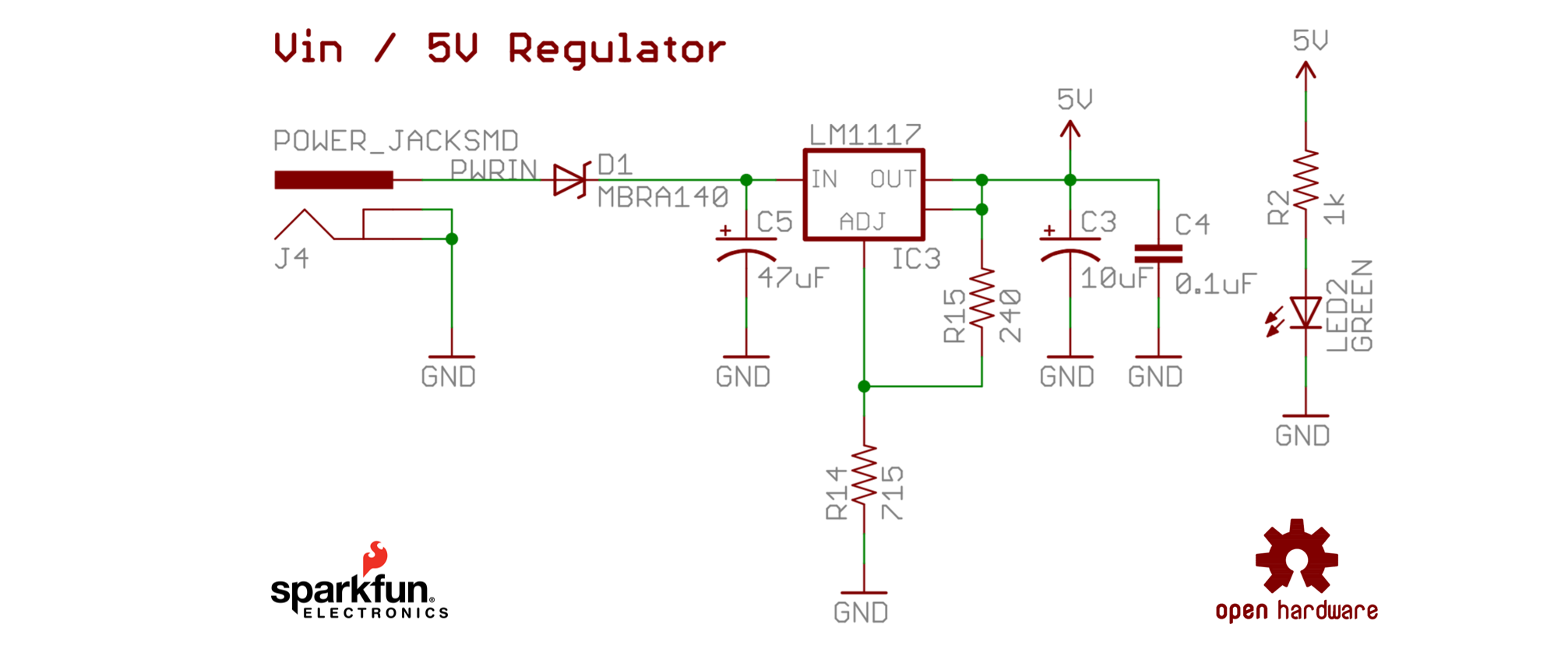
Figure. This circuit schematic is of the 5V voltage regulator on the SparkFun RedBoard, SparkFun’s open hardware version of the Arduino Uno R3 board. Notice how the schematic uses the voltage source and ground node symbols? A voltage regulator is a system designed to maintain a constant voltage and is used here to step down 7–15V source inputs to a constant 5V. The full schematic is here.
The circuit schematic above also has a number of other symbols, including polarized and non-polarized capacitors (two parallel lines), a zener diode, and the LM1117 linear regulator.
Tips for reading unfamiliar schematics
As you encounter more complex schematics—like the RedBoard example above—you may feel overwhelmed by unfamiliar symbols. Here are a few practical tips:
- Start with what you know. Identify the components you recognize (resistors, LEDs, battery/voltage source, ground) and trace current paths from those.
- Look for the power supply and ground symbols. These anchor the schematic and help you understand which nodes are at high vs. low potential.
- Don’t panic about unknown components. You don’t need to understand every symbol to get the overall picture. Focus on the topology—what’s connected to what—before worrying about individual component behavior.
- Read left-to-right, top-to-bottom. Many schematics (though not all) place the input on the left and output on the right, with positive voltage at the top and ground at the bottom.
- Consult the datasheet. If you encounter an IC (integrated circuit) you don’t recognize, search for its part number (e.g., “LM1117 datasheet”) to find its pinout and function.
Schematic building tools
There are a number of schematic building tools aimed at makers, each with their own tradeoffs.
-
Fritzing. Provides both pictorial (“breadboard”) plus schematic representations. Long a favorite in the maker and education communities, though the production version is now a paid download (€ 8). Free development builds are available on GitHub.
-
KiCad. A free, open-source EDA tool used widely in both hobbyist and professional settings. KiCad offers powerful schematic capture and PCB layout, with a large parts library. More full-featured (and more complex) than Fritzing, but excellent once you’re ready to go beyond breadboard prototyping.
-
Circuito.io. Has some very interesting auto-completion features—you select components and it automatically generates a wiring diagram and test code. Purely a web app. No simulation support.
-
Tinkercad Circuits. Allows you to design Arduino-based circuits, write code, and simulate. Does not provide schematic representations.
-
Wokwi. A new’ish and popular web-based simulator tailored for microcontrollers (Arduino, ESP32, Raspberry Pi Pico).
Activity: Building circuit diagrams in Fritzing
For your learning activity, we would like you to build both a pictorial representation and a schematic representation of the same circuit in the open-source hardware layout tool Fritzing.
Download and install Fritzing
While the production version of Fritzing is now € 8 (version 1.0.6), you can download free development versions on GitHub. The latest free development version is CD-548. Visit the GitHub Fritzing releases page and scroll down to CD-548, then click on the ‘Assets’ link, which will expand a download menu for compiled versions of Fritzing for various OSes. See image below.

Figure. Go to the GitHub Fritzing releases page, scroll down to CD-548, then click on the ‘Assets’ link to download a free development version of Fritzing.
Download and install Adafruit Fritzing library
Adafruit maintains an open-source repository on GitHub of all their custom electronic parts for Fritzing (cool!). If you’re using Adafruit parts in your projects, we strongly recommend downloading and installing the Adafruit Fritzing Library—just follow the installation instructions here!
Using Fritzing
Once you’ve downloaded and unzipped the Fritzing release, open it and follow this tutorial video. Together, we will make a simple LED-based circuit with a 9V battery, a switch, a resistor, and an LED. To complement the video, we also have this simple Fritzing PDF guide.
Figure. A video tutorial of using Fritzing to build a simple LED-based circuit.
Unfortunately, while you can create nice pictorial and schematic diagrams of circuits in Fritzing, you cannot simulate them (ugh, I know!). So, you have to use another tool for this.
For your prototyping journal
For your prototyping journal, take a screenshot of what you made following the tutorial video. Then save a new file, and make a simple modification to the circuit—it could be switching to a different color LED or adding in another part of the circuit. Take a screenshot of this new modified circuit and describe it, briefly, in your journal.
As usual, you should also report on any challenges or confusions you experienced!
Have fun!
Resources
-
How to Read a Schematic, sparkfun.com
-
From Schematic to Reality, beavisaudio.com
-
Appendix B: Schematics, John M. Hughes, Practical Electronics: Components and Techniques, O’Reilly Media, 2015
-
Schematic Diagrams, ITP videos by Jeff Feddersen on Vimeo
Next Lesson
In the next lesson, we will learn about Ohm’s Law, one of the most important and fundamental empirical laws in electrical circuits that relates voltage, current, and resistance together in a rather simple equation: \(I = \frac{V}{R}\).