Lesson 7: Breadboards
Table of Contents
- Inside a breadboard
- Examples
- Some breadboard tips
- Common breadboarding mistakes
- Video tutorial
- Breadboard voltage and current specifications
- Limitations
- Experimenting with breadboards in Tinkercad
- Activity
- Resources
- Next Lesson
Breadboards allow us to prototype physical computing circuits quickly and efficiently without soldering. They have standardized holes arranged in a grid that allow integrated circuits, resistors, LEDs, and other components to sit snugly in the board, and you use “jumper wires” to connect components together.
These so-called “solderless breadboards”—or just “breadboards” for short—dramatically simplify prototyping circuits. Before breadboards became common, prototypers had to painfully wrap wires around mounted conductive poles or screws (see the image below).
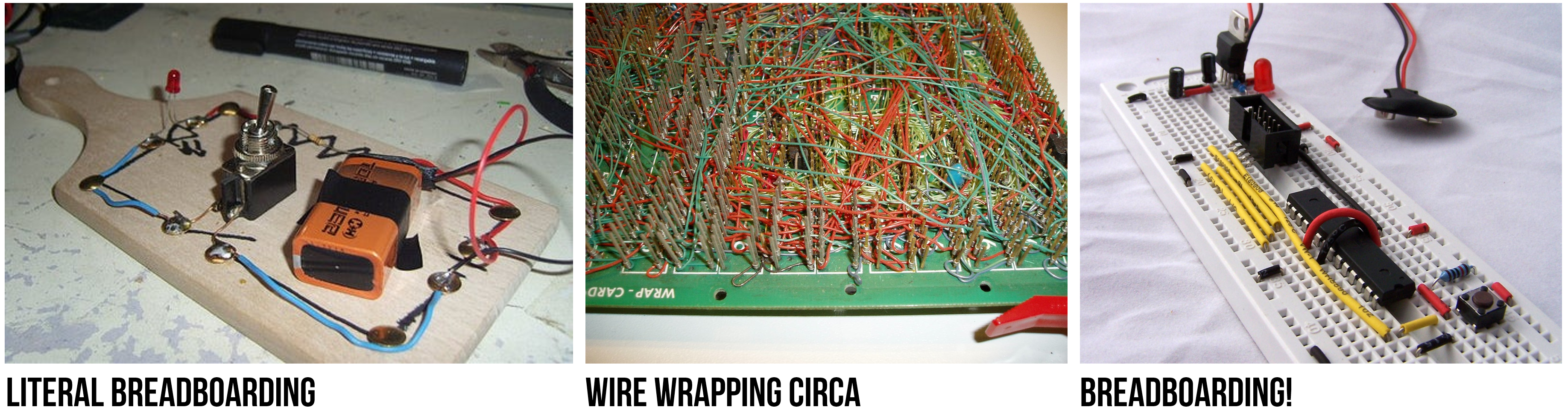 Figure. The left image is from an Instructable on “Using a Real Breadboard for Prototyping Your Circuit” and the center image is originally from Wikipedia (user Wikinaut); however, both images were found on Sparkfun.com’s breadboard tutorial.
That said, breadboards can be a bit confusing at first and do take time to get used to. In this lesson, we’ll learn about breadboards, prototype with them in the simulation environment called Tinkercad Circuits, and build some simple circuits with resistors and LEDs.
Inside a breadboard
If you tore open a breadboard, you would see a set of pre-wired columns and rows (internal metal strips). These pre-wired connections are exposed as holes on the top of the breadboard (arranged in a grid), which you can quickly and easily tap into to make circuits.
Unfortunately, it is not immediately clear which holes are pre-wired to one another—which introduces a lot of confusion and miswirings for novices. So, it’s important that you study and understand these breadboarding images (and also be patient with yourself as you’re learning—a very common and frustrating mistake for beginners is an ‘off-by-one’ error or misunderstanding how the embedded wiring in a breadboard works).
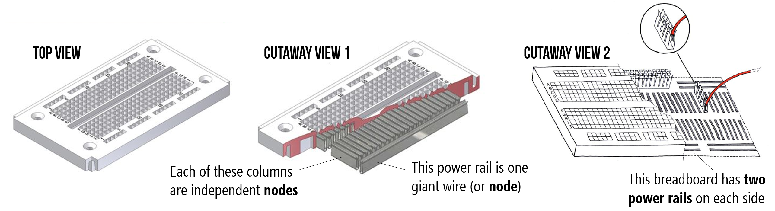 Figure. Images originally from here and here. Annotations in PowerPoint.
In the image below, we’ve highlighted where the pre-wired connections (those internal metal strips) exist. You can think of each of these highlighted lines as individual nodes. Just like the breadboards in your kit, this breadboard has two power rails on each side, individual columns for placing components, and a ravine (or center divider) in the middle that separates the columns on each side of the board. This gap is specifically sized so that DIP (dual in-line package) integrated circuits can straddle it with their legs on opposite sides.
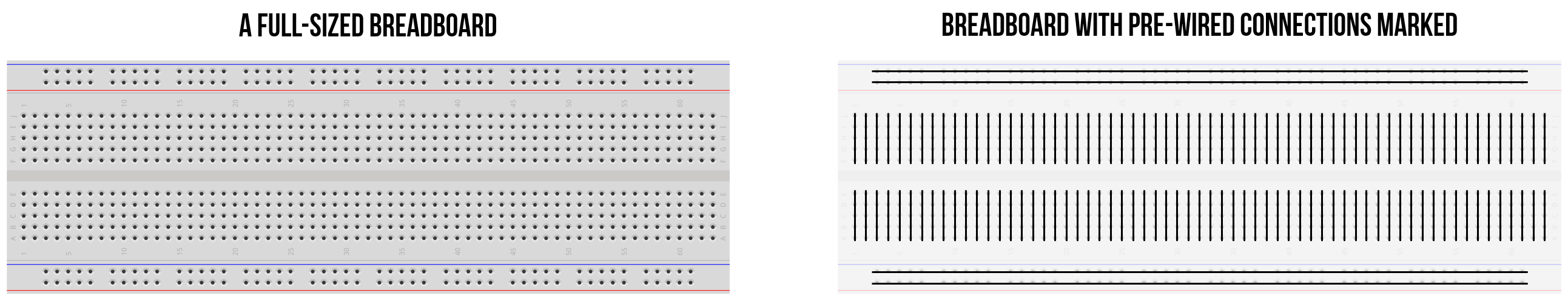 Figure. Breadboard image from Fritzing. Annotations in PowerPoint.
Examples
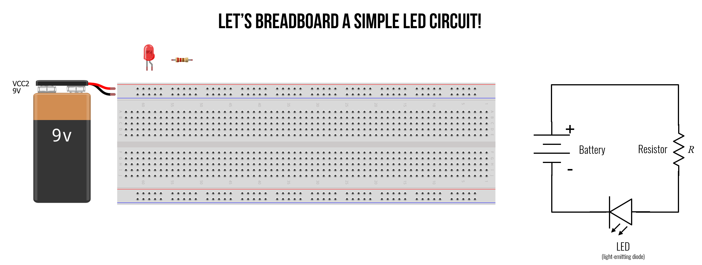
Let’s breadboard an LED-based circuit with a 9V power supply, a resistor, and a red LED. We’re going to build one variation step-by-step and then show other possibilities.
With breadboards, there are nearly infinite ways to build the same circuit. So, try to keep things clean and minimize the use of extraneous wires whenever possible. As we walk through this example and then show variations, check your understanding: what makes sense to you? Which breadboard variation is “cleanest” in your opinion and why?
Building variation 1
Let’s build our first breadboard circuit. In this version, we’re trying to keep things very clear. Consequently, we’re using more jumper wires than necessary. Let’s get started.
Step 1: Connect the voltage source
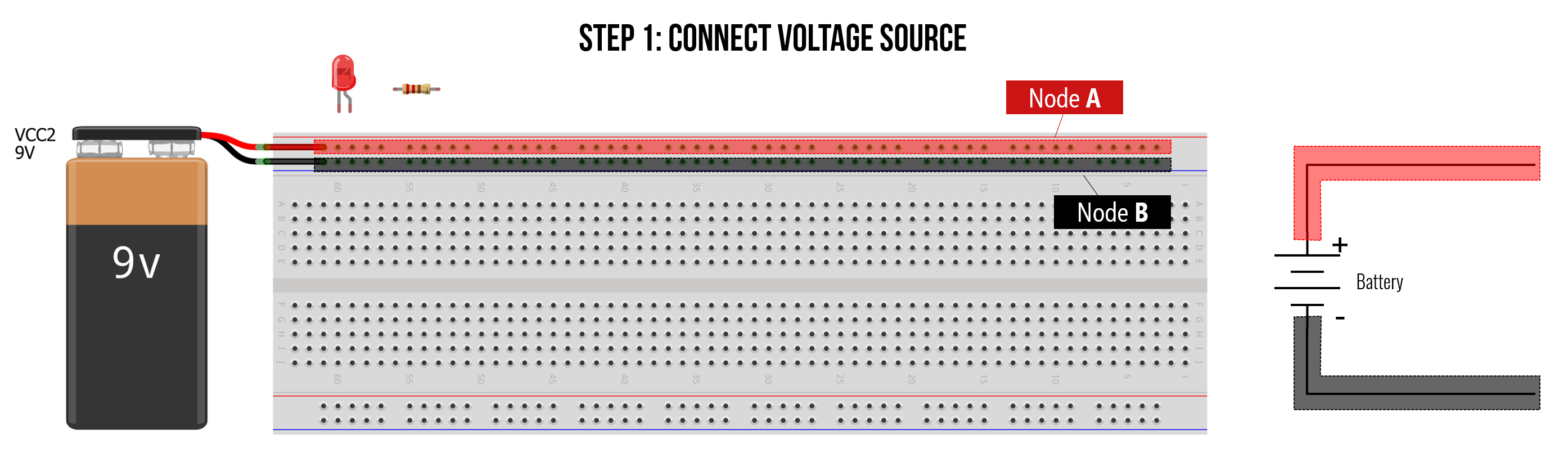
First, let’s connect the positive and negative terminals of the battery to the power rails. Notice how with just making two connections, we create two giant nodes (red for positive + and black for -). These two nodes are now easily tappable as we build out our circuit.
Typically, we would not connect the power rails to our voltage source until we’re ready to test something (it’s not good practice to breadboard with a live source!). But for educational purposes, it’s helpful to first start here and build the circuit outwards.
In general, do not connect your power source until you’ve finished building your circuit. Breadboarding with a live source is a common beginner mistake that can damage components.
Step 2: Add the resistor
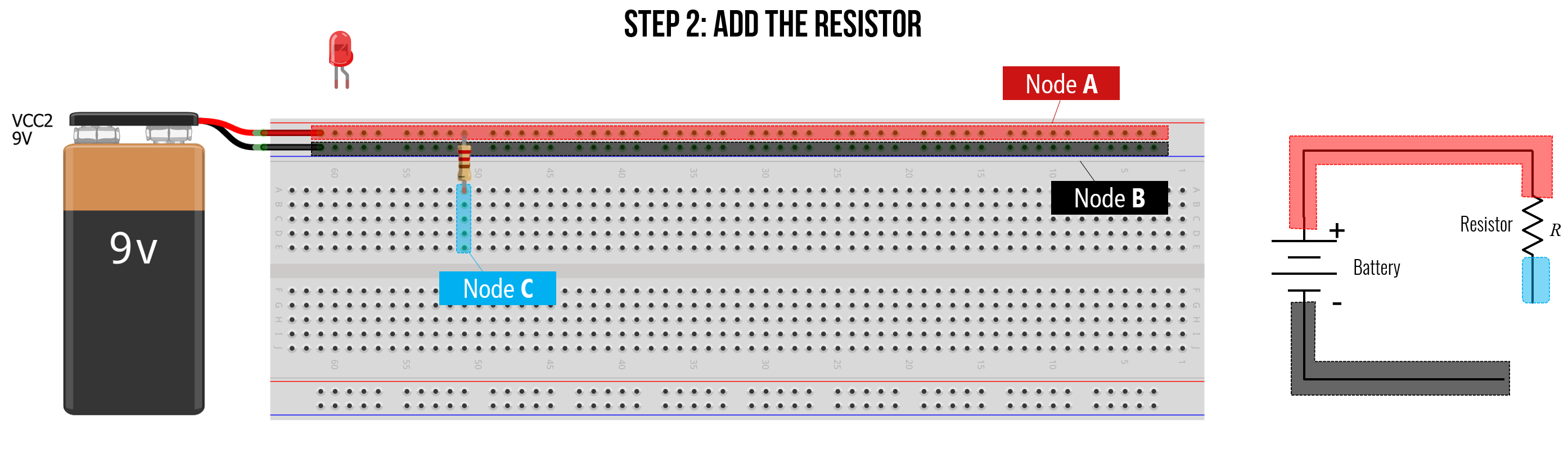
Second, let’s add in the resistor connecting one leg directly to the positive + power rail and the other to an arbitrary column on our breadboard. Notice how even though the bottom resistor leg is in just one hole, that entire column becomes the same node (Node C). Also note how Node C does not extend across the ravine in the middle of the board.
Step 3: Add the LED
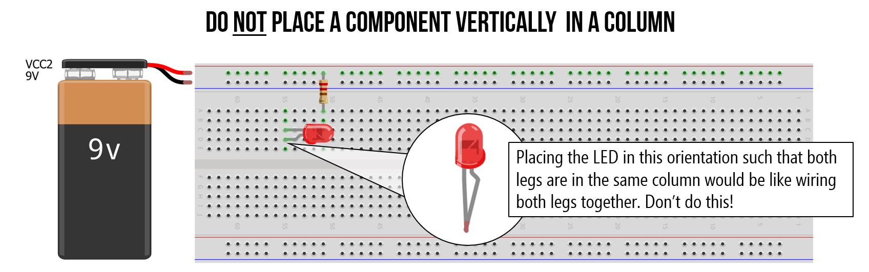
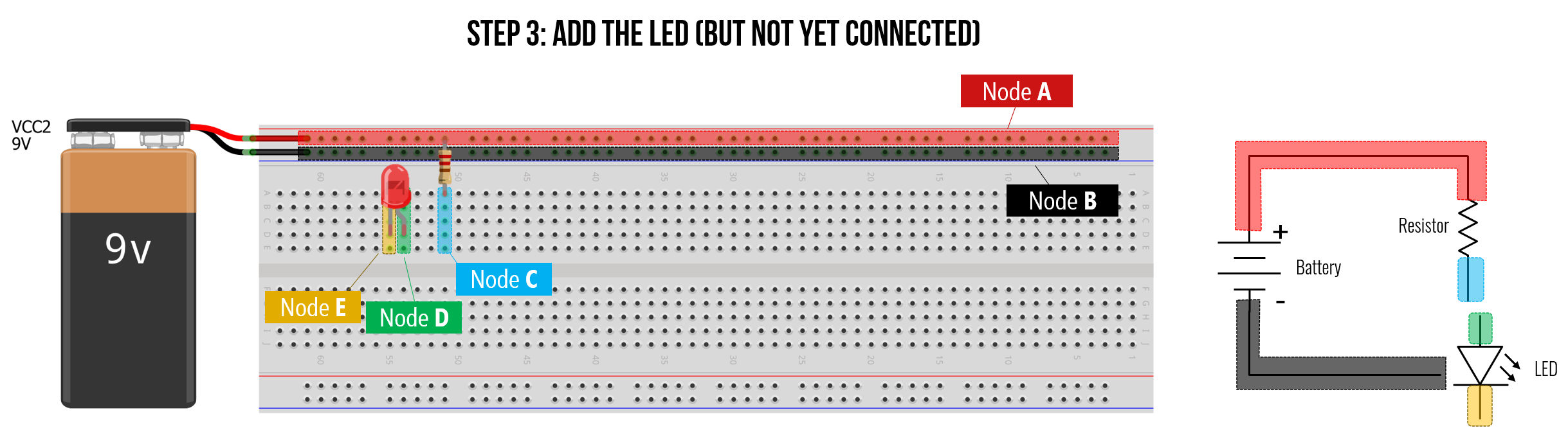
Third, let’s add in the LED. We can place it anywhere we want but let’s put it close to the resistor (since we know we’ll have to connect them). Importantly, we cannot put the LED in such that both legs are in the same column—this would short the LED since both legs would be electrically connected.
Instead, place the LED such that the legs span two columns, like this. Notably, the LED is not yet connected to anything in our circuit. It’s just sort of floating there in its own space. We’ll hook it up next.
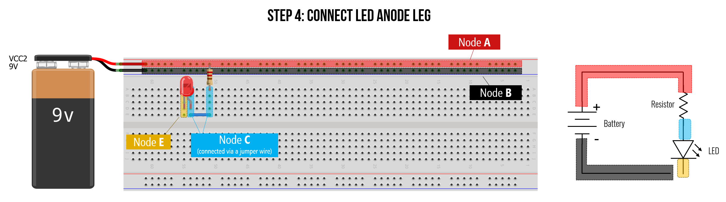
Step 4: Connect LED anode (+) leg
Now, let’s wire up the LED to our circuit starting with the LED anode (+) leg first (which must point towards the higher electric potential, i.e., towards the resistor and positive rail in our circuit).
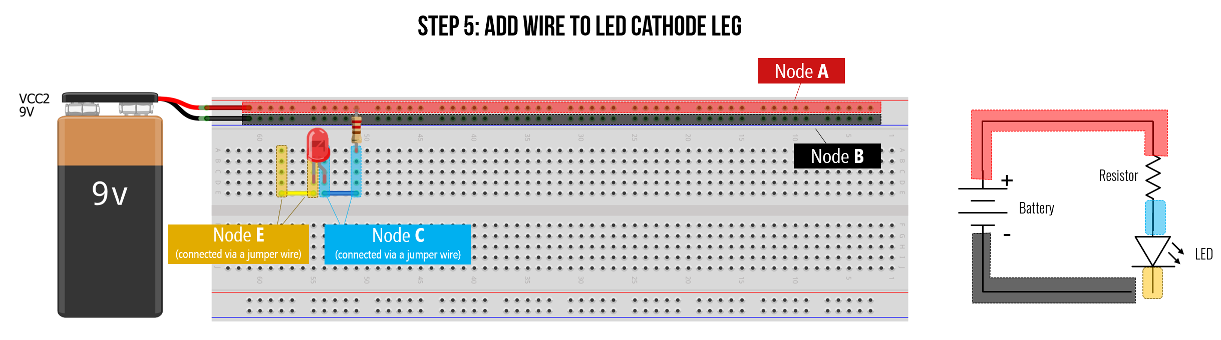
Step 5: Connect LED cathode (-) leg
Fifth, let’s wire up the LED cathode leg. In this case, we’ll create an intermediate wire connection to a different point of our breadboard just to keep things clean. However, we could just place a jumper wire from the cathode leg directly to the GND (-) power rail.
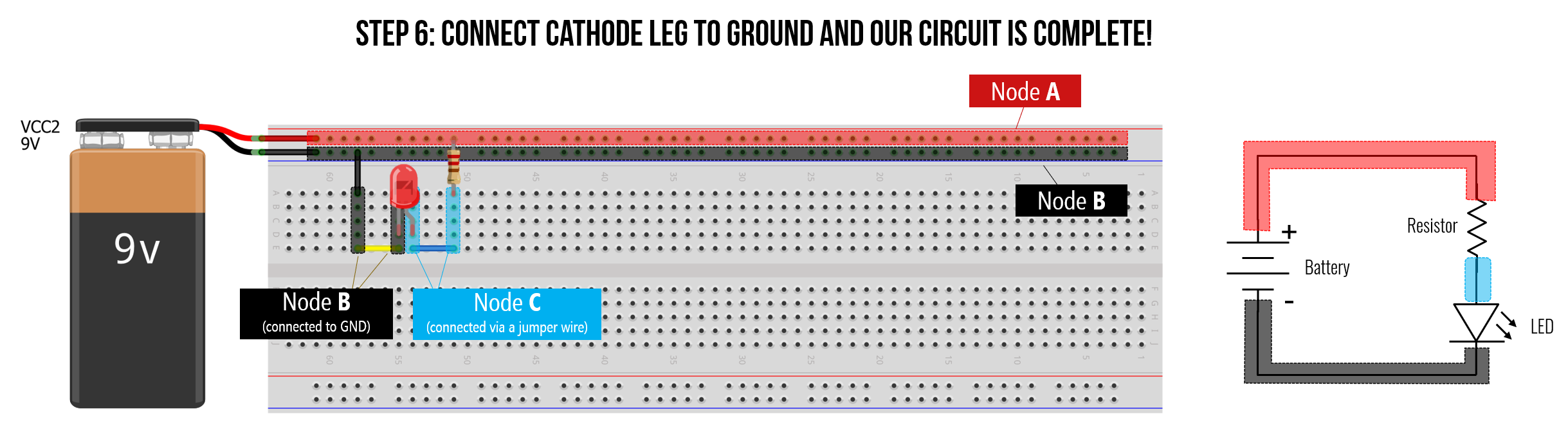
Step 6: Connect LED cathode (-) to ground
Finally, we can connect the LED cathode node to ground, thereby completing our circuit. Yay!
Does this breadboarded circuit make sense? Can you picture how current would flow through the breadboard?
Visualizing current through breadboard
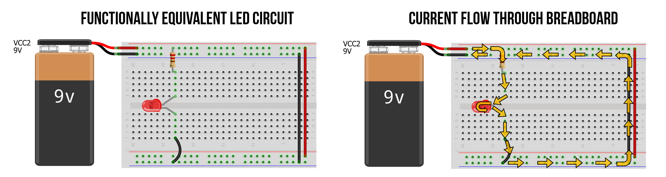
To further reinforce how a breadboard works, we’ve drawn two additional representations. The middle image below shows a schematic overlay on top of the breadboard. The image on the right shows overlaid arrows showing the path of conventional current. Is this what you visualized too? Why or why not?
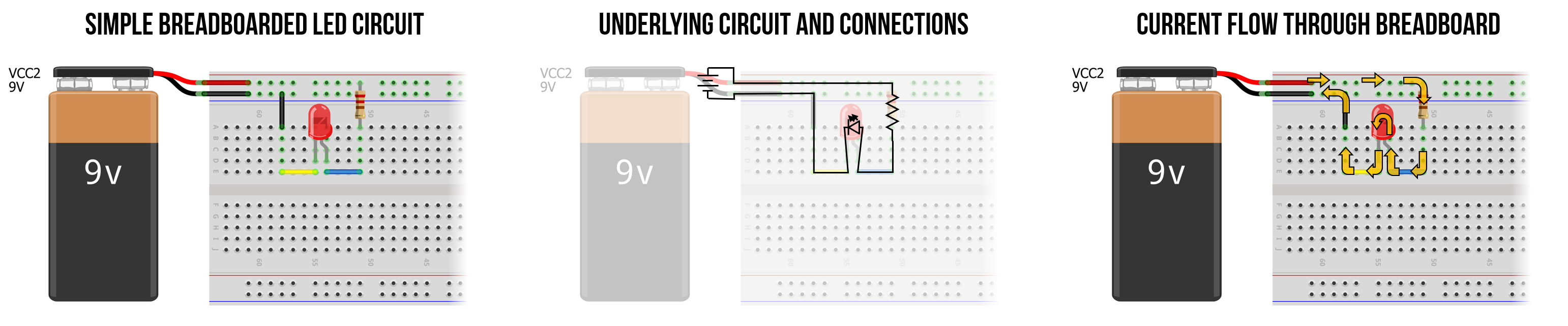 Figure. Made in Fritzing and PowerPoint.
Variation 2
Here’s another version of the same circuit but breadboarded differently. Again, with breadboards, part of what makes them powerful is their flexibility—but this also introduces many possibilities for breadboarding the same circuit (and this is just for one simple example!).
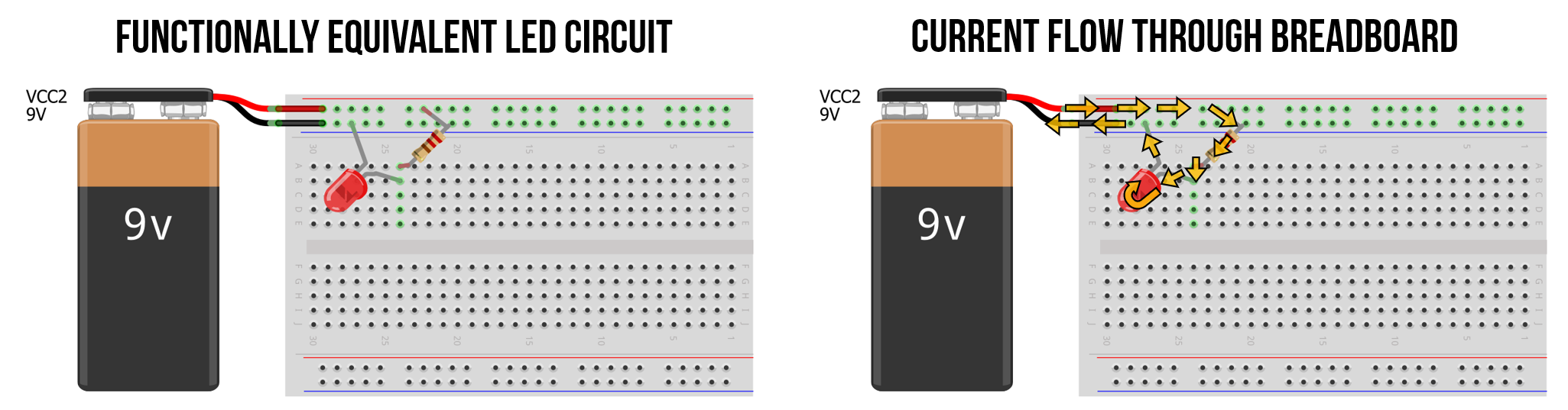
Variation 3
Again, the same circuit but breadboarded differently. This version uses no jumper wires and simply connects the resistor and LED directly to the power rails.
Some breadboard tips
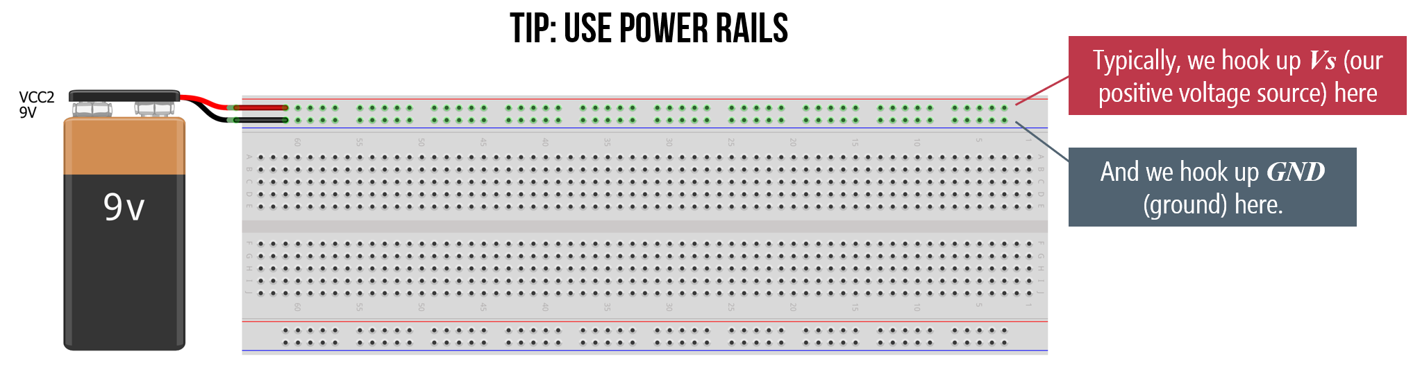
Tip 1: Use power rails
Connect your voltage source to the power rails first, then tap into them as needed rather than running separate wires from the source for each component.
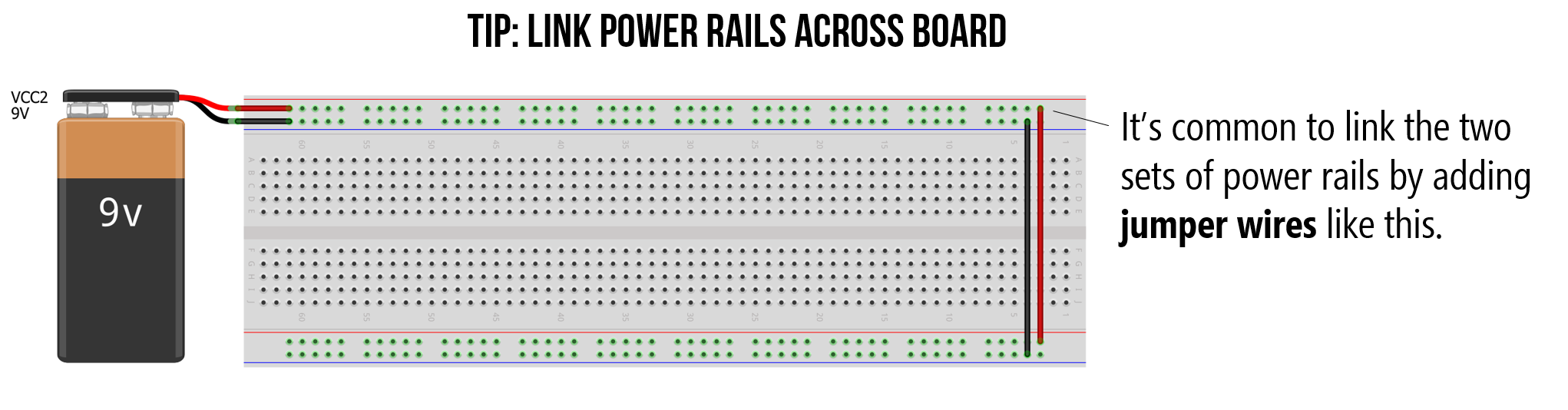
Tip 2: Link power rails across board
On larger breadboards, the power rails on the left and right sides may not be connected to each other. Use jumper wires to link them if you need power on both sides.
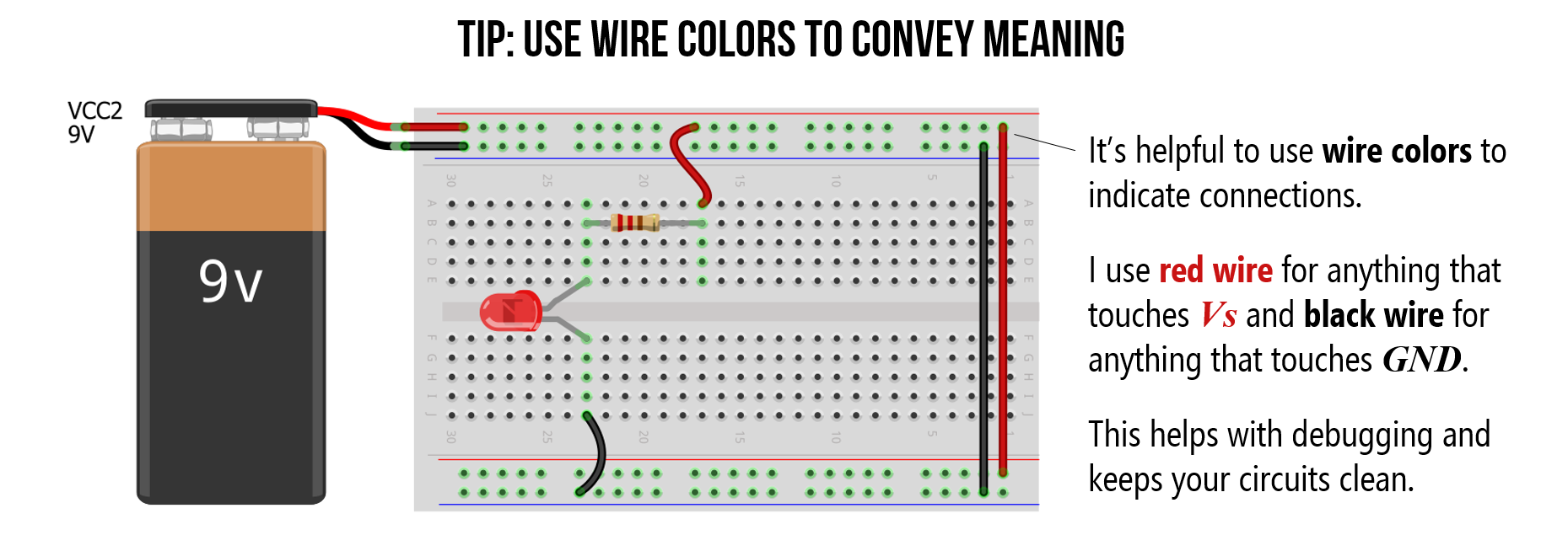
Tip 3: Use wire colors to convey meaning
Use red wires for positive voltage, black wires for ground, and other colors for signal connections. This makes debugging much easier.
Common breadboarding mistakes
As you start breadboarding, here are the most frequent errors to watch out for:
Off-by-one errors. You intend to connect two components in the same column, but one leg lands in the adjacent column. The circuit doesn’t work and everything looks correct—maddening! Double-check your column alignment, especially in the crowded middle of the board.
Shorting across the same column. Remember that all five holes in a vertical column are connected. If you place both legs of a component (like an LED or resistor) into the same column, you create a short circuit and the current will bypass the component entirely.
Straddling the ravine incorrectly. Remember that the ravine electrically separates the two halves of the board. If you place a component so that both legs are on the same side of the ravine (in two adjacent columns), that’s fine. But if you intended to bridge the ravine (like with an IC chip), make sure the legs are actually in the correct columns on each side.
Assuming power rails are continuous. On some larger breadboards, the power rails have a break in the middle (often marked by a gap in the colored line). If your circuit works on one half of the board but not the other, check whether your power rails are actually connected all the way across. When in doubt, use a jumper wire to bridge the gap.
Forgetting LED polarity. LEDs only work in one direction. If your LED doesn’t light up and your circuit looks correct, try flipping the LED around before troubleshooting anything else.
Video tutorial
If you’re still feeling lost, we highly recommend this breadboard tutorial video by Science Buddies.
Video. This video tutorial “How to use a breadboard” by Science Buddies offers a great introduction to breadboards.
Breadboard voltage and current specifications
Generally, breadboards are designed to work with low-voltage circuits (0–12V) and low amperages (under ~1A). Some breadboard listings claim ratings of “300V/3–5A”—but I’m highly skeptical of those numbers. If you need to prototype a circuit with higher voltages or currents exceeding ~500mA–1A, it’s better to use a perfboard and a soldering iron.
Limitations
Breadboards have a number of limitations. First, their connections can wear over time (as you push in and pull out components) leading to unreliable contact points. Second, the internal metal clips and contact points add parasitic resistance and capacitance. I’ve seen estimates of about 0.1Ω of contact resistance and a stray capacitance of 2–20 picofarads (pF) per connection (link, link). Finally, due to these factors, high-frequency digital circuits—that switch on/off voltages at ~16 MHz and beyond—won’t work reliably.
In physical computing, however, breadboards are often the perfect rapid prototyping tool.
When to move beyond breadboards. Breadboards are ideal for prototyping and learning, but once your design is finalized and you want something permanent, you’ll want to move to soldered connections. Options include perfboards (solder your components onto a board with pre-drilled holes), stripboards/veroboard (perfboards with pre-connected copper strips), or custom printed circuit boards (PCBs), which you can design in tools like KiCad and order from manufacturers for a few dollars. We won’t cover PCB design in this course, but it’s good to know the path forward.
Experimenting with breadboards in Tinkercad
To learn more about breadboards and gain experience with them before building physical circuits, let’s use Tinkercad Circuits to play around. Tinkercad makes it easy to rapidly prototype, build, and simulate circuits in a software environment. And for those who do not have access to electronic tools, Tinkercad also provides a simple multimeter and oscilloscope—so we can test and measure our circuits too!
One particularly useful feature for learning about breadboards is that Tinkercad auto-highlights connected nodes when you mouse over breadboard columns and rows, which helps build understanding before using a physical breadboard.
Step 1: Open Tinkercad Circuits
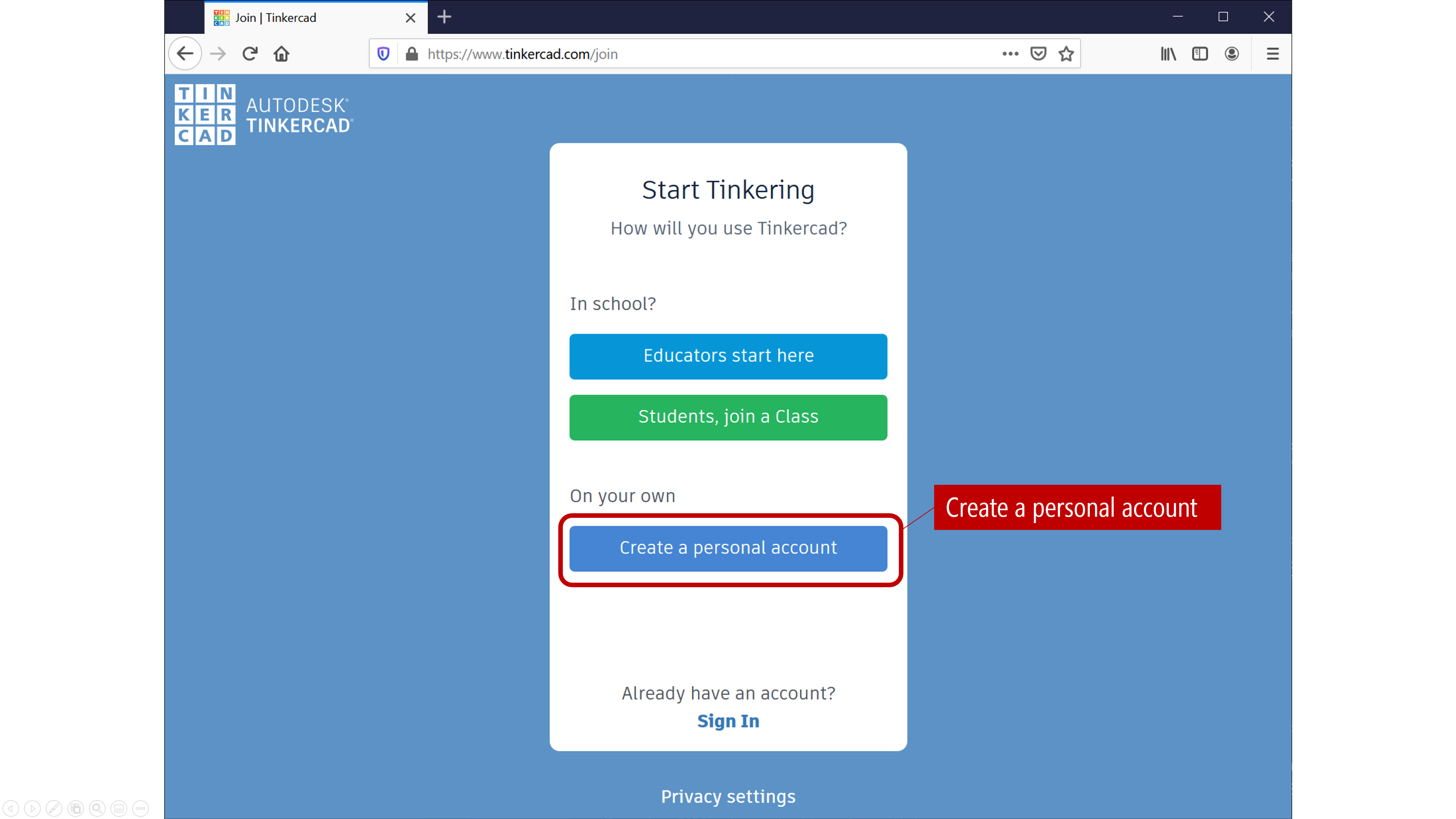
Visit tinkercad.com and login (if you already have an Autodesk account) or register if not. We are not using any of the “In School” features, so create a personal account:
Step 2: Create a new circuit
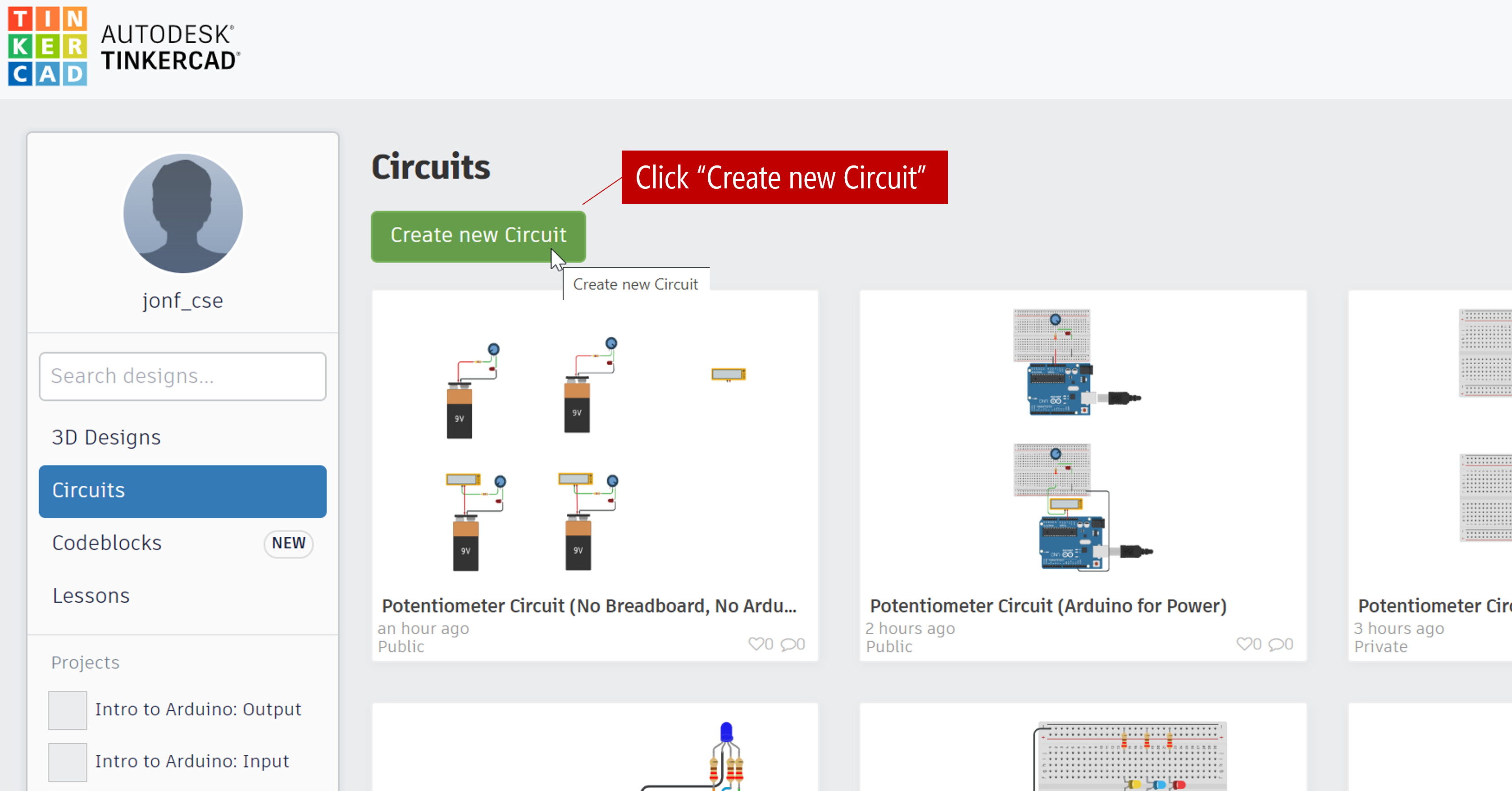
In your dashboard, click on “Circuits”:

Then click on “Create new Circuit”:
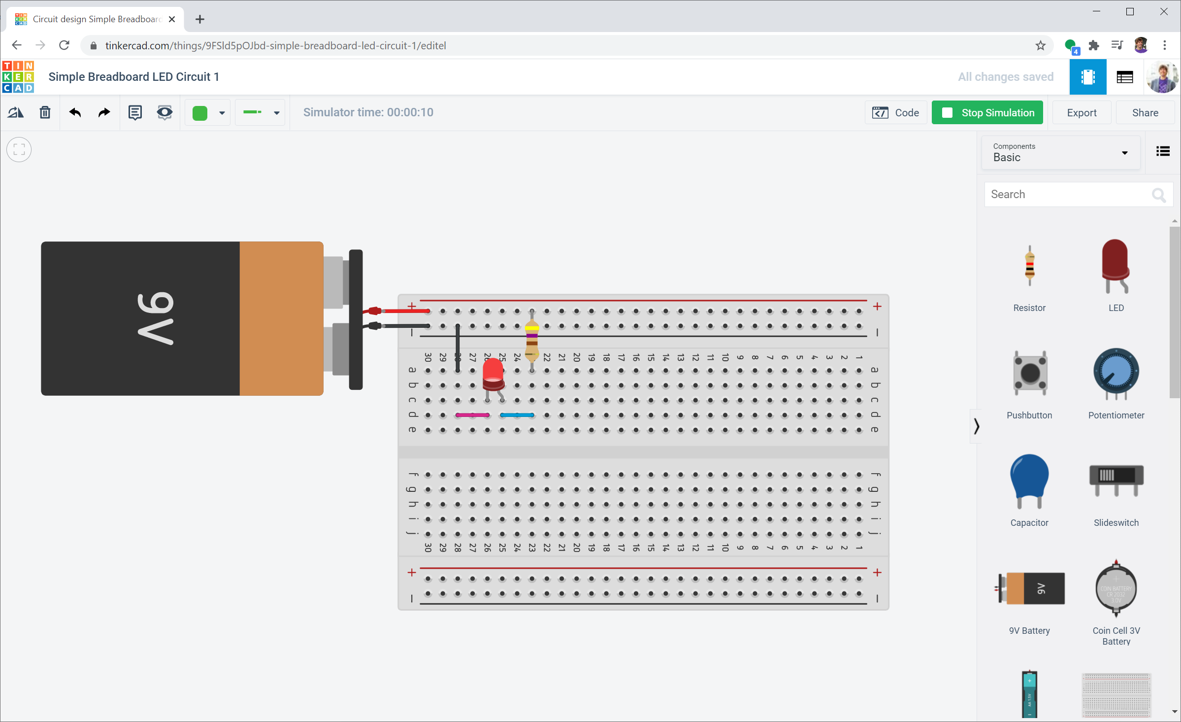
Step 3: Acquaint yourself with Tinkercad
Tinkercad works by dragging and dropping components from the right sidebar menu onto the Circuit canvas. You can click on the “Start Simulation” button to simulate circuits (in later lessons, we’ll show how you can even simulate circuits with and write code for Arduino in the Tinkercad environment).
Step 4: You can even embed created circuits onto webpages
Tinkercad also has a cool feature to embed working versions of your circuits onto webpages. Here’s a simple LED circuit with a 9V battery supply, a 470Ω resistor, and an LED. You can open this circuit in Tinkercad yourself and start to remix it as well!
Embedded Circuit. We’ve embedded a simple LED circuit made in Tinkercad. You can open it here and play with it and/or build on it.
Activity
For your prototyping journals, come up with three LED-based circuits and build them in Tinkercad Circuits—each circuit can either be a minor or major variation. The goal of this activity is to get comfortable with breadboards. Play around. What do you observe? Take screenshots, provide a brief description, and include a link to your Tinkercad circuit in your prototyping journal.
Then, select your two favorite ideas and actually build them using the components in your hardware kits (e.g., breadboard, 9V battery, resistors, LEDs). Using manual calculations for current draw, estimate how long your circuit will last on a 9V battery—assume 500 mAh at a 25mA discharge rate and ~400 mAh at a 50mA discharge rate down to 4.8 volts (9V Energizer Datasheet).
Note that you’ll need to use the alligator clips on the 9V battery to supply power to your breadboard rails. I suggest using the black alligator clip for the battery’s negative terminal, the red alligator clip for the battery’s positive terminal, and matching jumper wires to connect to your breadboard.
A Note on 9V Batteries: While convenient for simple LED breadboard circuits, standard 9V alkaline batteries have high internal resistance and very low capacity (~500 mAh) compared to AA or LiPo batteries. They struggle to supply quick bursts of current, which can cause sudden voltage drops that reset microcontrollers or fail to drive motors. As your projects get more complex, you will likely transition to 5V USB power banks or 3.7V LiPo batteries.
Resources
-
Setting Up a Breadboard, NYU ITP
-
How to use a breadboard, Science Buddies video
-
How to Use a Breadboard, Sparkfun.com
Next Lesson
In the next lesson, we will learn more about variable resistors and how to use them.