Lesson 4: p5.js Serial I/O
Table of Contents
- DisplayShapeOut: p5.js to Arduino
- DisplayShapeBidirectional: p5.js to Arduino and Arduino to p5.js
- Lesson Summary
- Exercises
- Next Lesson
Video. A preview of what we’ll build: DisplayShapeBidirectional, where p5.js buttons and physical Arduino buttons control a shape shared between the browser canvas and the OLED display. (live page, code)
OK, now we’re really rolling! We learned about serial communication, then how to use serial in our browsers (Web Serial!), and then how to do this with p5.js. And we’ve already made some cool proof-of-concept demos.
Let’s take this growing knowledge and momentum to create slightly more sophisticated programs. First, we’ll cover the case of using p5.js to control something on our Arduino (Computer → Arduino). Then we’ll introduce bidirectional communication (Computer ↔ Arduino) where the computer and Arduino work together to create a holistic interactive experience. 🎮
In this lesson, you will learn:
- How to send data from a p5.js web app to Arduino (
Computer → Arduino)- How to design a text-based serial protocol with comma-separated values
- How to parse incoming serial data on the Arduino side
- Essential debugging strategies for serial communication (echo-back, OLED debug output)
- How to build bidirectional communication (
Computer ↔ Arduino) with shared state- How to handle state synchronization between two devices
DisplayShapeOut: p5.js to Arduino
To begin, we’ll build a simple p5.js demo app that draws and resizes a selected shape (a circle, square, or triangle) based on the mouse’s x position and sends this shape data as a text-encoded comma-separated string over web serial: ("shapeType, shapeSize"). On the Arduino side, we’ll parse this string and draw the current shape and size on the OLED. Because the p5.js canvas size and the OLED screen size do not match, we’ll use a normalized size value between [0,1] where 0 is the smallest size and 1 is the maximum size. Shape type is encoded as 0 for circle, 1 for square, and 2 for triangle.
Here’s a small sneak preview of what the final interactive experience will look like.
Video. A demonstration of the p5.js app DisplayShapeOut and Arduino sketch DisplayShapeIn.ino. The p5.js app sends a shapeType and a shapeSize as a comma-separated text string to Arduino via web serial. The DisplayShapeIn.ino program parses this text and draws a shape with the appropriate size to the OLED. I did not use my regular recording setup for this because OBS Studio + my document camera have a noticeable lag. You can view, edit, play with the DisplayShapeOut code in the p5.js online editor or from our GitHub (live page, code)
Creating DisplayShapeOut in p5.js
As with our previous lesson, we’ll begin with our SerialTemplate. If you’re using VSCode, copy SerialTemplate and rename the folder to DisplayShapeOut. If you’re using the p5.js online editor, simply open this project, Serial Template, and rename your project to DisplayShapeOut.
Overview of DisplayShapeOut functionality
Let’s go over some of DisplayShapeOut’s primary functionality. We want the user to:
-
Select a current shape (circle, triangle, or rectangle). We’ll do this by enumerating through them in order via a mouse press action
-
Change the size of the shape. We’ll do this by tracking the mouse’s x position and mapping it to size
-
Send shape data over serial. Each time either the current shape or size changes, we need to send an update over serial. We’ll do this using our serial.js library
Draw and dynamically resize shape
We’ll build this up piece-by-piece. First, we’ll focus on the p5.js shape drawing code and then add in web serial. Let’s start by supporting a single shape type and adding in the resizing via x mouse position (similar to this part of our previous lesson).
Add in the following top-level variables:
const MIN_SHAPE_SIZE = 10;   // minimum shape size in pixels
const MAX_SHAPE_MARGIN = 10; // when shape is at max size, the margin to edge of canvas
let maxShapeSize = -1;       // the maximum shape size
let curShapeSize = 10;       // the current shape size
We use the prefix const to indicate read-only variables and let for block-scoped mutable variables.
Now initialize the maxShapeSize based on the canvas width/height in setup():
function setup(){
  ...
  maxShapeSize = min(width, height) - MAX_SHAPE_MARGIN;
  ...
}
Update the draw() function to actually draw our shape (a circle, for now).
function draw() {
  background(100);

  fill(250);
  noStroke();
  const xCenter = width / 2;
  const yCenter = height / 2;
  circle(xCenter, yCenter, curShapeSize);
}
Finally, we need to change curShapeSize based on the x position of the mouse:
function mouseMoved(){
  curShapeSize = map(mouseX, 0, width, MIN_SHAPE_SIZE, maxShapeSize);

  // mouseMoved() is called even when mouse not directly over our canvas
  // so make sure to constrain to just the min,max size. If you don't do this
  // your circle may grow larger than you expect. Try it out!
  curShapeSize = constrain(curShapeSize, MIN_SHAPE_SIZE, maxShapeSize);
}
That’s it! We made an initial interactive shape app. Save your work and try it out with VSCode’s Live Server or simply hit the play button in the p5.js editor.
Here’s a live demo from the p5.js online editor. Move your mouse over the canvas below to watch the circle change in size proportionally to the mouse’s x position.
Code. The initial code skeleton for interactively sizing a shape based on the mouse’s x position. You can view, edit, and play with the code here.
Add in support for multiple shapes
Now, let’s add in support for rendering more shapes: the square and triangle. We need a variable to track the current shape type and a method for the user to switch between shapes:
To track the current shape type, we’ll use a JavaScript Object—a flexible, foundational data type in JavaScript. Anything that is not a primitive data type in JavaScript—e.g., things that are not a String, Boolean, Number, etc.—is a JavaScript Object. In this case, we’ll simply treat this Object as a key/value store, so let’s call it mapShapeTypeToShapeName where the variable indicates “mapping” a shape type (0, 1, 2) to a shape name (circle, square, triangle). And we’ll track the current shape type via curShapeType.
const mapShapeTypeToShapeName = {
  0: "Circle",
  1: "Square",
  2: "Triangle"
};

let curShapeType = 0;        // track current shape type
So, mapShapeTypeToShapeName defines the three shapes and their key/value relationship and curShapeType tracks the current shape as 0 (for circle), 1 (for square), and 2 (for triangle).
For selecting the shape type, there are many possibilities—we could draw small iconic representations of a circle, square, and triangle and switch shape types when these are clicked (like buttons). But we’ll do something even simpler: increment curShapeType on each mouse click.
function mouseClicked() {
  curShapeType++;
  if(curShapeType >= Object.keys(mapShapeTypeToShapeName).length){
    curShapeType = 0;
  }

  // Your template may have also had this code in mouseClicked()
  // Comment out for now.
  //if (!serial.isOpen()) {
  //  serial.connectAndOpen(null, serialOptions);
  //}
}
Finally, we need to update our draw() function to draw the three shape types:
function draw() {
  background(100);
  fill(250);
  noStroke();
  const xCenter = width / 2;
  const yCenter = height / 2;
  const halfShapeSize = curShapeSize / 2;

  switch(curShapeType){
    case 0: // draw circle
      circle(xCenter, yCenter, curShapeSize);
      break;
    case 1: // draw square
      rectMode(CENTER);  // See: https://p5js.org/reference/#/p5/rectMode
      square(xCenter, yCenter, curShapeSize);
      break;
    case 2: // draw triangle
      let x1 = xCenter - halfShapeSize;
      let y1 = yCenter + halfShapeSize;

      let x2 = xCenter;
      let y2 = yCenter - halfShapeSize;

      let x3 = xCenter + halfShapeSize;
      let y3 = y1;

      triangle(x1, y1, x2, y2, x3, y3)
  }
}
For user friendliness, let’s drop in some instructions as well. At the end of the draw() function, display some text that says “Mouse click to change the shape”:
function draw() {
  ...

  // Some instructions to the user
  noStroke();
  fill(255);
  const tSize = 14; // text size
  const strInstructions = "Mouse click to change the shape";
  textSize(tSize);
  let tWidth = textWidth(strInstructions);
  const xText = width / 2 - tWidth / 2;
  text(strInstructions, xText, height - tSize + 6);
}
Alright, we did it! Now check out your work by loading it with Live Server or in the p5.js online editor. Here’s a live demo:
Code. Changing shapes by mouse clicking. Code here.
Add in web serial output
Finally, the last piece is to output shape type and shape size via web serial. To limit needless serial writes, we’ll track the last shape type and size and only send out new data when these values have changed.
First, let’s add a serial write function called serialWriteShapeData(shapeType, shapeSize), which takes in a shape type and shape size and outputs them over web serial as text-encoded data.
async function serialWriteShapeData(shapeType, shapeSize) {
  if (serial.isOpen()) {
    // Convert the shape size into a fraction between [0, 1] inclusive
    let shapeSizeFraction = (shapeSize - MIN_SHAPE_SIZE) / (maxShapeSize - MIN_SHAPE_SIZE);

    // Format the text string to send over serial. nf simply formats the floating point
    // See: https://p5js.org/reference/#/p5/nf
    let strData = shapeType + ", " + nf(shapeSizeFraction, 1, 2);
    serial.writeLine(strData);
  }
}
Notably, we convert the shape size, which is in pixels, to a normalized value between [0, 1] called shapeSizeFraction—this is what we’ll transmit over serial and interpret on the Arduino side.
Now, let’s update the mouseClicked() function to handle opening and connecting with web serial or, if a connection has been made, to increment curShapeType and send that new data over serial by calling our new serialWriteShapeData() function.
function mouseClicked() {
  if (!serial.isOpen()) {
    // If the serial connection is not opened, begin open/connect sequence
    try {
      serial.connectAndOpen(null, serialOptions);
    } catch (error) {
      console.error("Serial connection failed:", error);
    }
  }else{
    // Otherwise, increment shape type
    curShapeType++;
    if(curShapeType >= Object.keys(mapShapeTypeToShapeName).length){
      curShapeType = 0;
    }

    // Given that shape type just changed, write out new values to serial
    serialWriteShapeData(curShapeType, curShapeSize);
  }
}
Let’s also update the instructions to the user so they know that mouse clicking is state dependent:
function draw(){
  ...
  // Some instructions to the user
  noStroke();
  fill(255);
  const tSize = 14;
  let strInstructions = "";
  if(serial.isOpen()){
    strInstructions = "Mouse click anywhere to change the shape";
  }else{
    strInstructions = "Click anywhere to connect with serial"
  }
  textSize(tSize);
  let tWidth = textWidth(strInstructions);
  const xText = width / 2 - tWidth / 2;
  text(strInstructions, xText, height - tSize + 6);
}
Finally, we need to update the mouseMoved() method to call serialWriteShapeData() on a new shape size:
function mouseMoved(){
  let lastShapeSize = curShapeSize;
  curShapeSize = map(mouseX, 0, width, MIN_SHAPE_SIZE, maxShapeSize);
  curShapeSize = constrain(curShapeSize, MIN_SHAPE_SIZE, maxShapeSize);

  if(lastShapeSize != curShapeSize){
    serialWriteShapeData(curShapeType, curShapeSize);
  }
}
And we’re done with the p5.js app! You can view, edit, play with the code in the p5.js online editor or from our GitHub (live page, code).
Creating DisplayShapeIn in Arduino
We could design many different types of Arduino apps that read in "shapeType, shapeSize" off serial and do something interesting. For example, we could use this info to set the paddle size and ball type (circle, square, triangle) in an OLED-based Breakout game. For this Arduino app, however, let’s simply replicate the p5.js app visual experience. This might sound hard but you’re OLED experts by now—you got this!
But how should we begin?
The key is to start simply and build up your app step-by-step, testing incrementally each step of the way.
A simple beginning and debugging strategies
Let’s begin our Arduino app simply by echo’ing the incoming data back on serial. Remember, you cannot use the Arduino IDE’s Serial Monitor once your p5.js app connects with your Arduino over serial. See error message in the figure below.
Only one program can access a serial port at a time. Once your p5.js app connects to the Arduino via Web Serial, the Arduino IDE’s Serial Monitor cannot open the same port. You’ll see a “Port busy” error. Close the browser tab (or disconnect serial in your web app) before trying to use Serial Monitor.
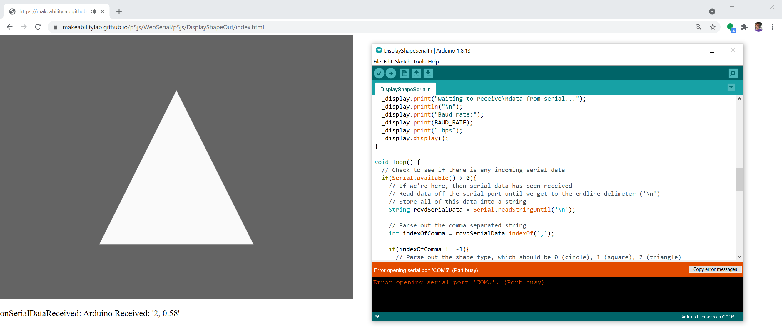 Figure. This figures shows the p5.js app DisplayShapeOut running and connected to the Arduino via web serial. Consequently, we cannot open and use the Arduino IDE’s Serial Monitor tool (
Tools -> Serial Monitor) because only one program can connect to a serial port at a time. When we try, we get an error printed in the Arduino IDE console (right image) that says “Error opening serial port ‘COM5’. (Port busy)”
So, instead, let’s program our p5.js app to read incoming serial data and print it out—a web-based Serial Monitor! Luckily, our p5.js SerialTemplate code already does that. In the template, we simply have:
function onSerialDataReceived(eventSender, newData) {
  console.log("onSerialDataReceived", newData);
  pHtmlMsg.html("onSerialDataReceived: " + newData);
}
Which prints incoming data sent by Arduino to console and also updates the handy pHtmlMsg HTML element so you can see the info on your webpage (you could comment this out, of course).
So, the simplest Arduino sketch to start with could be an “echo back” program like:
const long BAUD_RATE = 115200;
void setup() {
  Serial.begin(BAUD_RATE);
}

void loop() {
  // Check to see if there is any incoming serial data
  if(Serial.available() > 0){
    // Read data off the serial port until we get to the endline delimiter ('\n')
    String rcvdSerialData = Serial.readStringUntil('\n');

    // Echo the data back on serial (for debugging purposes)
    Serial.print("Arduino Received: '");
    Serial.print(rcvdSerialData);
    Serial.println("'");
  }
}
Code. Simple serial echo back program for Arduino (EchoBackSerialIn.ino on GitHub).
This echo technique is a crucial debugging tool. So, make sure you understand it!
The echo-back technique is one of the most useful serial debugging strategies. By having the Arduino send back what it received, you can verify that (1) data is being transmitted successfully, (2) the data arrives in the expected format, and (3) parsing works correctly. We also recommend using the OLED display for intermediate debug output—it’s like having a mini serial monitor right on your breadboard!
Watch out for
readStringUntil()timeouts.Serial.readStringUntil('\n')is a blocking function—if no newline arrives, it waits for the default timeout of 1000 ms before returning. In interactive apps, a missing or malformed newline means your entireloop()stalls for a full second. If you notice lag, consider addingSerial.setTimeout(50);insetup()to reduce the timeout to 50ms. This way, a dropped packet causes only a brief hiccup instead of a one-second freeze.
A simple OLED circuit
We’ll wire up the OLED using I2C as we did in our OLED lesson. For our lesson, we’ll use the Arduino Leonardo but some of you may choose to use the Adafruit Huzzah32 (ESP32). We provide both I2C wirings below.
The Arduino Leonardo Wiring
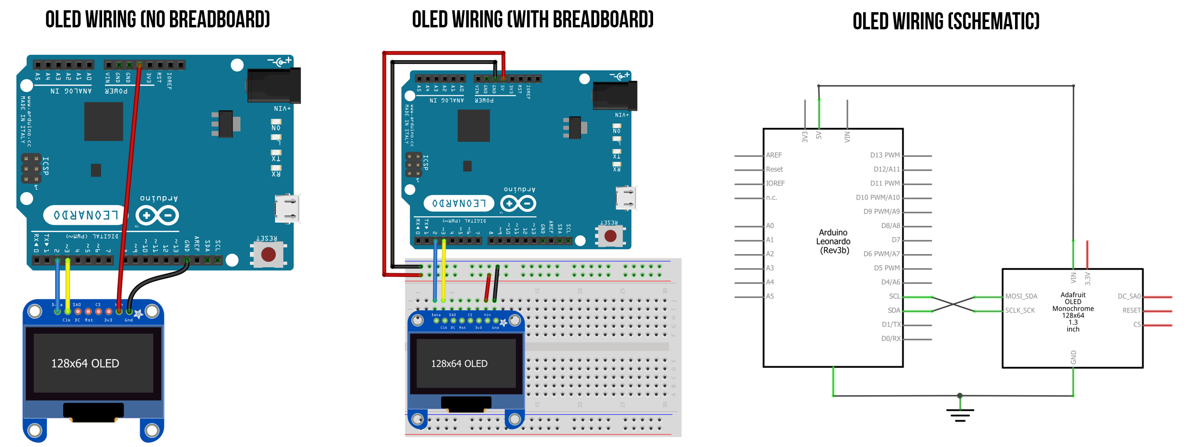 Figure Wiring the Adafruit OLED display with I2C requires only four wires. For my wire colors, I used the standard STEMMA QT color coding: blue for data (SDA), yellow for clock (SCL), black for ground (GND), and red for the voltage supply (5V). Note that the I2C pins will differ depending on your board. For example, on the Arduino Uno, they are A4 (SDA) and A5 (SCL) rather than digital pins 2 (SDA) and 3 (SCL) as they are for the Leonardo.
The ESP32 Wiring
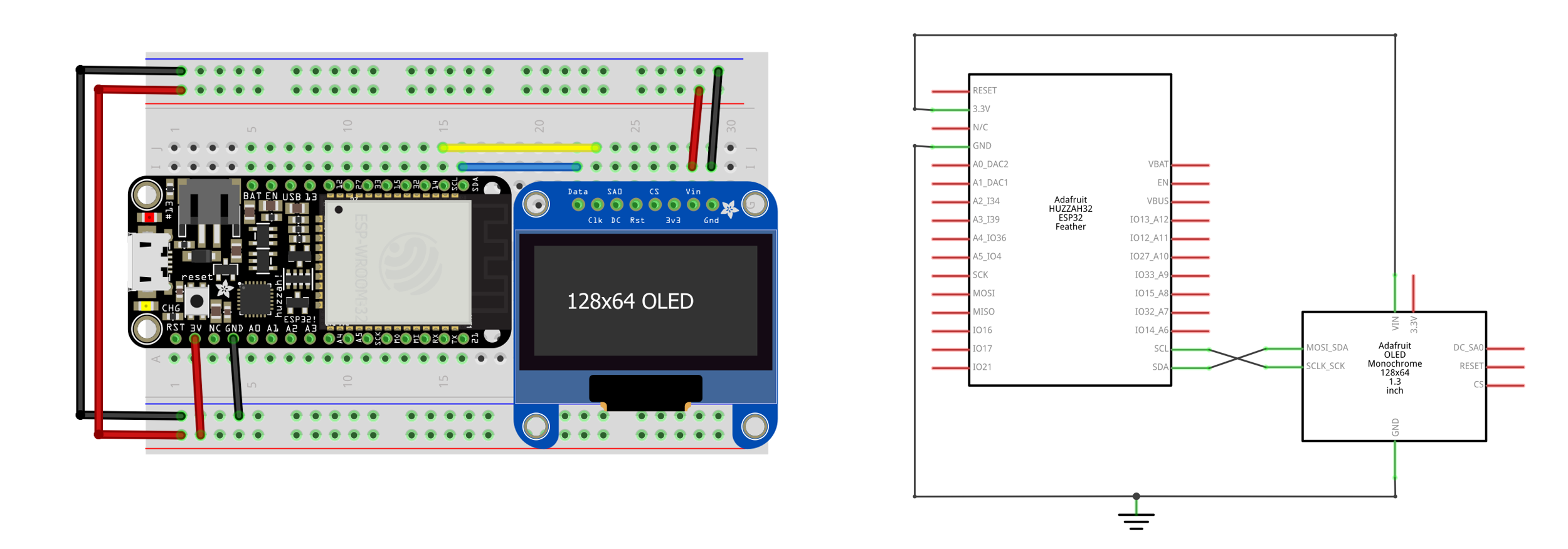 Figure. Wiring diagram for the Adafruit Huzzah32 ESP32 board with OLED. Note that the ESP32 has silk-printed SCL and SDA pins at the top-right corner.
Using an ESP32-S3? The I2C pin locations may differ from the Huzzah32 shown above. Check your board’s pinout diagram. Also remember to use
Serial.begin(115200)and setbaudRate: 115200in your p5.js code.
Add in OLED and debug printlns
Now, let’s program the OLED to print out some debugging information. Add the following OLED-required declarations at the top:
#include <Wire.h>
#include <Adafruit_GFX.h>
#include <Adafruit_SSD1306.h>

#define SCREEN_WIDTH 128 // OLED display width, in pixels
#define SCREEN_HEIGHT 64 // OLED display height, in pixels

// Declaration for an SSD1306 display connected to I2C (SDA, SCL pins)
#define OLED_RESET     4 // Reset pin # (or -1 if sharing Arduino reset pin)
Adafruit_SSD1306 _display(SCREEN_WIDTH, SCREEN_HEIGHT, &Wire, OLED_RESET);
In setup(), initialize the OLED and print out a “Waiting for serial…” message. We’ll also show the baud rate, which is a useful reminder in case you set a different value on the p5.js side.
const long BAUD_RATE = 115200;
void setup() {
  Serial.begin(BAUD_RATE);

  // SSD1306_SWITCHCAPVCC = generate display voltage from 3.3V internally
  if(!_display.begin(SSD1306_SWITCHCAPVCC, 0x3D)) { // Address 0x3D for 128x64
    Serial.println(F("SSD1306 allocation failed"));
    for(;;); // Don't proceed, loop forever
  }

  _display.clearDisplay();
  _display.setTextSize(1);      // Normal 1:1 pixel scale
  _display.setTextColor(SSD1306_WHITE); // Draw white text
  _display.setCursor(0, 0);     // Start at top-left corner
  _display.print("Waiting to receive\ndata from serial...");
  _display.println("\n");
  _display.print("Baud rate:");
  _display.print(BAUD_RATE);
  _display.print(" bps");
  _display.display();
}
Now, in loop(), add in the OLED-based debug printouts:
void loop() {
  // Check to see if there is any incoming serial data
  if(Serial.available() > 0){
    // If we're here, then serial data has been received
    // Read data off the serial port until we get to the endline delimiter ('\n')
    // Store all of this data into a string
    String rcvdSerialData = Serial.readStringUntil('\n');

    // Display data on OLED for debugging purposes
    _display.clearDisplay();
    _display.setCursor(0, 0);
    _display.setTextSize(1);
    _display.println("RECEIVED:\n");
    _display.setTextSize(3);
    _display.println(rcvdSerialData);
    _display.display();

    // Echo the data back on serial (for debugging purposes)
    Serial.print("Arduino Received: '");
    Serial.print(rcvdSerialData);
    Serial.println("'");
  }
}
Here’s a video demonstration of what we have so far: the full DisplayShapeOut p5.js app (live page, code) running with an intermediate version of DisplayShapeSerialIn.ino, which simply echos back received data and displays some debugging output to the OLED screen.
Video. Testing the C++ echo-back code for Arduino with the p5.js app DisplayShapeOut (live page, code). You can view this intermediate version of DisplayShapeSerialIn.ino here.
Parse serial data and update OLED debug output
So far, so good!
But now we actually need to parse the incoming serial text data into useful typed variables. Let’s do that and update our OLED-based debug output. Again, it’s useful to construct our program step-by-step testing along the way.
Update the code inside of if(Serial.available() > 0) in loop() to include parsing. There are many possible parsing approaches; however, we are going to take advantage of Arduino’s String object and functions like indexOf() and substring() to look for commas and parse out our data. We showed a similar technique in our Intro to Serial lesson.
For now, we’ll display both the raw data received over serial as well as the parsed data. Once we’re confident we have this working, we’ll remove this debug output.
String rcvdSerialData = Serial.readStringUntil('\n');

// Parse out the comma separated string
int indexOfComma = rcvdSerialData.indexOf(',');
if(indexOfComma != -1){
  // Parse out the shape type, which should be 0 (circle), 1 (square), 2 (triangle)
  String strShapeType = rcvdSerialData.substring(0, indexOfComma);
  int shapeType = strShapeType.toInt();

  // Parse out shape size fraction, a float between [0, 1]
  String strShapeSize = rcvdSerialData.substring(indexOfComma + 1, rcvdSerialData.length());
  float curShapeSizeFraction = strShapeSize.toFloat();

  // Display data for debugging purposes
  _display.clearDisplay();
  _display.setCursor(0, 0);
  _display.println("RECEIVED:");
  _display.println(rcvdSerialData);

  // Display parsed data
  _display.println("\nPARSED:");
  _display.print("Shape Type: ");
  _display.println(shapeType);
  _display.print("Shape Size: ");
  _display.print(curShapeSizeFraction);
  _display.display();
}
Great, now let’s upload this to the Arduino and test our two apps thus far. Does the parsing work?
Video. Testing the C++ parsing code for Arduino with the p5.js app DisplayShapeOut (live page, code). You can view this intermediate version of DisplayShapeSerialIn.ino here.
Test parsing code via Serial Monitor
Our Arduino program does not know where the incoming data from its serial port is coming from. It could be coming from any application. We can use this to our advantage for testing!
Let’s close our p5.js tab in our web browser to ensure it’s disconnected from the Arduino. Now, open up the Serial Monitor and input data into the Serial Monitor. When testing, it’s a good idea to enter both properly formed and malformed data. Make sure to test edge cases too! See video below.
Video. Using the Arduino IDE’s Serial Monitor to test our parsing code. Using the Serial Monitor is an easy, convenient way to test your serial input and parsing code on the Arduino.
Write drawing code
Awesome! We’re almost done.
Let’s pivot from reading and parsing serial input to writing our OLED-based drawing code. As we’ve previously mentioned the Adafruit GFX drawing API is not significantly different from the p5js drawing API. Note the similarities below!
First, let’s introduce some shape related types and variables:
// New enum for tracking shape types
enum ShapeType {
  CIRCLE,
  SQUARE,
  TRIANGLE,
  NUM_SHAPE_TYPES
};

ShapeType _curShapeType = CIRCLE; // tracks current shape type
float _curShapeSizeFraction = -1; // tracks current shape fraction

const int MIN_SHAPE_SIZE = 4;     // min shape size
int _maxShapeSize;                // max shape size (dependent on display width/height)
We also need to initialize _maxShapeSize in setup():
void setup(){
  ...
  _maxShapeSize = min(_display.width(), _display.height());
  ...
}
Update our relevant parsing code to use our new global variables _curShapeType and _curShapeSizeFraction. Let’s also add in some boundary checking to ensure that the shape size fraction is between [0, 1].
...
if(indexOfComma != -1){
  // Parse out the shape type, which should be 0 (circle), 1 (square), 2 (triangle)
  String strShapeType = rcvdSerialData.substring(0, indexOfComma);
  int shapeType = strShapeType.toInt();
  _curShapeType = (ShapeType)shapeType;

  // Parse out shape size fraction, a float between [0, 1]
  String strShapeSize = rcvdSerialData.substring(indexOfComma + 1, rcvdSerialData.length());
  _curShapeSizeFraction = strShapeSize.toFloat();

  // Boundary check shape size fraction
  if(_curShapeSizeFraction < 0){
    _curShapeSizeFraction = 0;
  }else if(_curShapeSizeFraction > 1){
    _curShapeSizeFraction = 1;
  }
}
...
Now, let’s add our drawShape(ShapeType shapeType, float fractionSize) function, which draws a circle, square, or triangle depending on the passed in shapeType at the appropriate size (fractionSize).
void drawShape(ShapeType shapeType, float fractionSize){
  _display.clearDisplay();

  int shapeSize = MIN_SHAPE_SIZE + fractionSize * (_maxShapeSize - MIN_SHAPE_SIZE);
  int halfShapeSize = shapeSize / 2;
  int xCenter = _display.width() / 2;
  int yCenter = _display.height() / 2;
  int xLeft =  xCenter - halfShapeSize;
  int yTop =  yCenter - halfShapeSize;

  // Render the appropriate shape
  if(shapeType == CIRCLE){
    _display.fillRoundRect(xLeft, yTop, shapeSize, shapeSize, halfShapeSize, SSD1306_WHITE);
  }else if(shapeType == SQUARE){
    _display.fillRect(xLeft, yTop, shapeSize, shapeSize, SSD1306_WHITE);
  }else if(shapeType == TRIANGLE){
    int x1 = xCenter - halfShapeSize;
    int y1 = yCenter + halfShapeSize;

    int x2 = xCenter;
    int y2 = yCenter - halfShapeSize;

    int x3 = xCenter + halfShapeSize;
    int y3 = y1;

    _display.fillTriangle(x1, y1, x2, y2, x3, y3, SSD1306_WHITE);
  }

  _display.display();
}
Finally, we need to call drawShape(), which we’ll do so at the end of loop():
void loop() {
  ...

  // if no data has arrived, shape fraction will be < 0
  if(_curShapeSizeFraction > 0){
    drawShape(_curShapeType, _curShapeSizeFraction);
  }
}
That’s it! You can see our full implementation on GitHub as DisplayShapeSerialIn.ino.
Full end-to-end demo
We did it! Here’s the full end-to-end demo.
Video. A demonstration of the p5.js app DisplayShapeOut and Arduino sketch DisplayShapeIn.ino. You can view, edit, play with the DisplayShapeOut code in the p5.js online editor or from our GitHub (live page, code)
DisplayShapeBidirectional: p5.js to Arduino and Arduino to p5.js
The above example demonstrated how to transmit data from p5.js to Arduino via text-encoded serial communication but did not send any commands from Arduino to p5.js. So, let’s extend our code to communicate information bidirectionally (from p5.js to Arduino and Arduino to p5.js)!
Again, there are many possibilities but let’s keep things simple. We’ll add two buttons on the Arduino side to select the shape type and a new drawing mode (fill vs. outline). We can also change these variables on the p5.js side via mouse clicks: left click to change the shape type (same as before) and right click to change the drawing mode.
Here’s a quick sneak peek at what the two apps will look like:
Video. A brief end-to-end demo of the p5.js app DisplayShapeBidirectional (live page, code) and the Arduino sketch DisplayShapeSerialBidirectional.ino.
Notably, we are using momentary buttons for the Arduino input rather than input devices or sensors that maintain physical state like a potentiometer because fixed physical states could get out of sync with p5.js.
Updating our p5.js code
To begin, make a copy of the DisplayShapeOut p5.js folder and rename it to something like DisplayShapeBidirectional. Now, let’s add in support for the draw mode, update our parsing, and modify our instructions to the user.
Adding the fill/outline draw mode
For the fill vs. outline draw mode, we’ll add in an additional state tracking variable called curShapeDrawMode:
const mapShapeDrawMode = {
  0: "Fill",
  1: "Outline",
};

let curShapeDrawMode = 0; // Fill as default
The draw mode can be set either by right clicking the mouse or from incoming Arduino data (from web serial). Let’s handle the former (right-mouse clicking) first.
According to the p5.js docs, the mouseClicked() function is only guaranteed to be called when the left mouse button is pressed and released. Thus, we cannot rely on this mouseClicked() for changing the draw mode. Instead, we’ll add our state tracking into mousePressed().
function mousePressed() {
  // Only update states if we're connected to serial
  if (serial.isOpen()) {
    if (mouseButton == RIGHT) {
      // Switch between fill and outline mode based on right click
      curShapeDrawMode++;
      if (curShapeDrawMode >= Object.keys(mapShapeDrawMode).length) {
        curShapeDrawMode = 0;
      }
    } else {
      curShapeType++;
      if (curShapeType >= Object.keys(mapShapeTypeToShapeName).length) {
        curShapeType = 0;
      }
    }
    serialWriteShapeData(curShapeType, curShapeSize, curShapeDrawMode);
  }
}
Notice that we also moved the shapeType tracking here too.
Add new instructions to the user
In draw(), update the instructions to the user to include info about both left-clicking and right-clicking:
function draw(){
  ...

  // Some instructions to the user
  noStroke();
  fill(255);
  const tSize = 14;
  let strInstructions = "";
  if (serial.isOpen()) {
    strInstructions = "Left click to change the shape. Right click to change fill/outline";
  } else {
    strInstructions = "Click anywhere to connect with serial"
  }
  textSize(tSize);
  let tWidth = textWidth(strInstructions);
  const xText = width / 2 - tWidth / 2;
  text(strInstructions, xText, height - tSize + 6);
}
Update the serialWriteShapeData function and callers
We also need to update our serialWriteShapeData() function to receive and write out three variables: shapeType, shapeSize, and shapeDrawMode instead of two as before:
async function serialWriteShapeData(shapeType, shapeSize, shapeDrawMode) {
  if (serial.isOpen()) {
    let shapeSizeFraction = (shapeSize - MIN_SHAPE_SIZE) / (maxShapeSize - MIN_SHAPE_SIZE);

    // Setup strData with three comma separated variables
    let strData = shapeType + ", " + nf(shapeSizeFraction, 1, 2) + ", " + shapeDrawMode;

    // Write out the data to serial
    serial.writeLine(strData);
  }
}
And make sure to also update the serialWriteShapeData() call in mouseMoved() to use three parameters as well:
function mouseMoved() {
  ...
  serialWriteShapeData(curShapeType, curShapeSize, curShapeDrawMode);
  ...
}
Add onSerialDataReceived parsing code
Finally, we need to add code that parses incoming serial data into shapeType, shapeSize, and shapeDrawMode. For this, we’ll add a new aspect to our Arduino → Computer communication protocol. Let’s say that any line of text transmitted with a # prefix will be ignored and considered debugging output. This way, we can continue to use our p5.js web app for output debugging while still parsing useful information.
Recall that our web serial library has an event called SerialEvents.DATA_RECEIVED, which we subscribe to in setup() and hook up a method called onSerialDataReceived(newData):
function setup() {
  ...
  serial.on(SerialEvents.DATA_RECEIVED, onSerialDataReceived);
  ...
}
Let’s now update that onSerialDataReceived method!
function onSerialDataReceived(eventSender, newData) {
  //console.log("onSerialDataReceived", newData);
  pHtmlMsg.html("onSerialDataReceived: " + newData);

  // Check if data received starts with '#'. If so, ignore it
  // Otherwise, parse it! We ignore lines that start with '#'
  if (!newData.startsWith("#")) {
    // Data format is ShapeType, ShapeDrawMode
    const indexOfComma = newData.indexOf(",");
    if (indexOfComma != -1) {
      let strShapeType = newData.substring(0, indexOfComma).trim();
      let strShapeDrawMode = newData.substring(indexOfComma + 1, newData.length).trim();
      let newShapeType = parseInt(strShapeType);
      let newShapeDrawMode = parseInt(strShapeDrawMode);

      // If data valid, set new shape type
      if (newShapeType in mapShapeTypeToShapeName) {
        curShapeType = newShapeType;
      }

      // if shape draw mode valid, set new draw mode
      if (newShapeDrawMode in mapShapeDrawMode) {
        curShapeDrawMode = newShapeDrawMode;
      }
    }
  }
}
And that’s it! Here’s our full implementation as DisplayShapeBidirectional in GitHub (live page here).
Updating our Arduino code and circuit
Shifting now to the Arduino side. Let’s add in two buttons to our Arduino circuit: one button to iterate through shape type and another to iterate through draw modes. We’ll hook them up to GPIO pins 4 and 5 respectively with internal pull-up resistors.
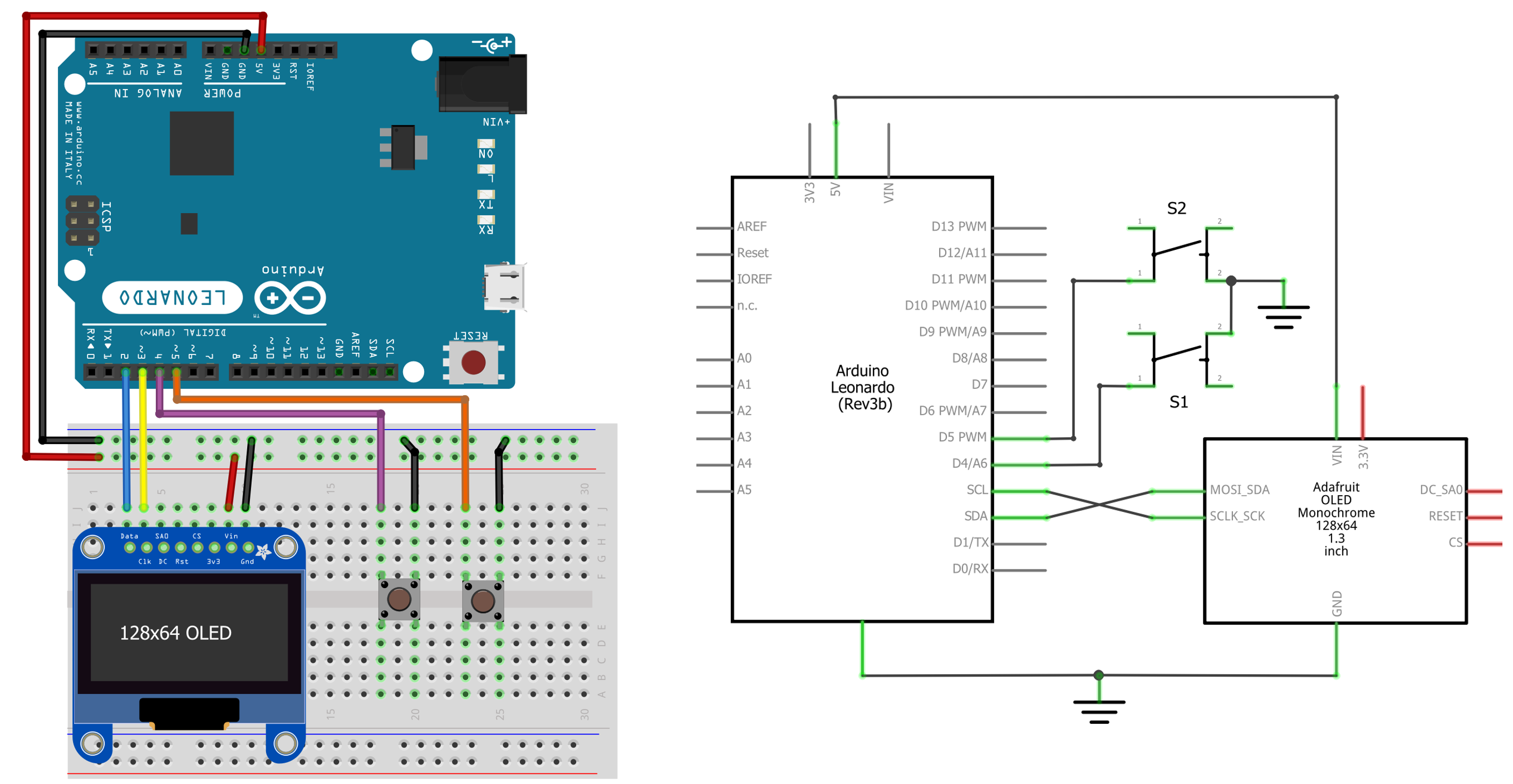 Figure. The Arduino Leonardo circuit with two buttons hooked up to pins 4 and 5 using the Arduino’s internal pull-up resistors. So, by default, they are in a
 HIGH state and will be pulled LOW upon button press.
Add draw mode support
For the code, let’s begin by adding draw mode support:
enum DrawMode{
  FILL,
  OUTLINE,
  NUM_DRAW_MODES
};

DrawMode _curDrawMode = FILL;
And update our drawShape() function to accept three variables and draw the shapes accordingly (either filled or as outlines):
void drawShape(ShapeType shapeType, float fractionSize, DrawMode curDrawMode){
  _display.clearDisplay();

  int shapeSize = MIN_SHAPE_SIZE + fractionSize * (_maxShapeSize - MIN_SHAPE_SIZE);
  int halfShapeSize = shapeSize / 2;
  int xCenter = _display.width() / 2;
  int yCenter = _display.height() / 2;
  int xLeft =  xCenter - halfShapeSize;
  int yTop =  yCenter - halfShapeSize;

  if(shapeType == CIRCLE){
    if(curDrawMode == FILL){
      _display.fillRoundRect(xLeft, yTop, shapeSize, shapeSize, halfShapeSize, SSD1306_WHITE);
    }else{
      _display.drawRoundRect(xLeft, yTop, shapeSize, shapeSize, halfShapeSize, SSD1306_WHITE);
    }
  }else if(shapeType == SQUARE){
    if(curDrawMode == FILL){
      _display.fillRect(xLeft, yTop, shapeSize, shapeSize, SSD1306_WHITE);
    }else{
      _display.drawRect(xLeft, yTop, shapeSize, shapeSize, SSD1306_WHITE);
    }
  }else if(shapeType == TRIANGLE){
    int x1 = xCenter - halfShapeSize;
    int y1 = yCenter + halfShapeSize;

    int x2 = xCenter;
    int y2 = yCenter - halfShapeSize;

    int x3 = xCenter + halfShapeSize;
    int y3 = y1;

    if(curDrawMode == FILL){
      _display.fillTriangle(x1, y1, x2, y2, x3, y3, SSD1306_WHITE);
    }else{
      _display.drawTriangle(x1, y1, x2, y2, x3, y3, SSD1306_WHITE);
    }
  }

  _display.display();
}
Add in support for buttons
Add in a new method called checkButtonPresses() that reads the two buttons, sets the global variables _curShapeType and _curDrawMode accordingly, and sends them over serial.
void checkButtonPresses(){
  // Read the shape selection button (active LOW)
  int shapeSelectionButtonVal = digitalRead(SHAPE_SELECTION_BUTTON_PIN);
  int lastShapeType = _curShapeType;
  if(shapeSelectionButtonVal == LOW && shapeSelectionButtonVal != _lastShapeSelectionButtonVal){
    // Increment the shape type
    _curShapeType = (ShapeType)((int)_curShapeType + 1);

    // Reset back to CIRCLE if we've made it to NUM_SHAPE_TYPES
    if(_curShapeType >= NUM_SHAPE_TYPES){
      _curShapeType = CIRCLE;
    }
  }

  // Read the shape draw mode button val (active LOW)
  int shapeDrawModeButtonVal = digitalRead(SHAPE_DRAWMODE_BUTTON_PIN);
  int lastDrawMode = _curDrawMode;
  if(shapeDrawModeButtonVal == LOW && shapeDrawModeButtonVal != _lastDrawModeButtonVal){
    // Increment the draw mode
    _curDrawMode = (DrawMode)((int)_curDrawMode + 1);

    // Reset back to FILL if we've made it to NUM_DRAW_MODES
    if(_curDrawMode >= NUM_DRAW_MODES){
      _curDrawMode = FILL;
    }
  }

  // Send new shape type and shape draw mode back over serial
  if(lastShapeType != _curShapeType || lastDrawMode != _curDrawMode){
    Serial.print(_curShapeType);
    Serial.print(", ");
    Serial.println(_curDrawMode);
  }

  // Set last button values (so nothing happens if user just holds down a button)
  _lastShapeSelectionButtonVal = shapeSelectionButtonVal;
  _lastDrawModeButtonVal = shapeDrawModeButtonVal;
}
We can test our new button and drawing code regardless of serial input. So, let’s do that now:
Video. Testing an intermediate version of our Arduino code (in GitHub here).
Update parsing code to support draw mode
Finally, we need to update the serial parsing code to parse three comma separated values rather than just two: shapeType, shapeSizeFraction, and drawMode. Let’s move all of this serial code into its own function called checkAndParseSerial():
void checkAndParseSerial(){
  // Check to see if there is any incoming serial data
  if(Serial.available() > 0){
    // If we're here, then serial data has been received
    // Read data off the serial port until we get to the endline delimiter ('\n')
    // Store all of this data into a string
    String rcvdSerialData = Serial.readStringUntil('\n');

    // Parse out the comma separated string
    int startIndex = 0;
    int endIndex = rcvdSerialData.indexOf(',');
    if(endIndex != -1){
      // Parse out the shape type, which should be 0 (circle), 1 (square), 2 (triangle)
      String strShapeType = rcvdSerialData.substring(startIndex, endIndex);
      int shapeType = strShapeType.toInt();
      _curShapeType = (ShapeType)shapeType;

      // Parse out shape size fraction, a float between [0, 1]
      startIndex = endIndex + 1;
      endIndex = rcvdSerialData.indexOf(',', startIndex);
      String strShapeSize = rcvdSerialData.substring(startIndex, endIndex);
      _curShapeSizeFraction = strShapeSize.toFloat();

      if(_curShapeSizeFraction < 0){
        _curShapeSizeFraction = 0;
      }else if(_curShapeSizeFraction > 1){
        _curShapeSizeFraction = 1;
      }

      // Parse out draw mode 0 (fill), 1 (outline)
      startIndex = endIndex + 1;
      endIndex = rcvdSerialData.length();
      String strDrawMode = rcvdSerialData.substring(startIndex, endIndex);
      int drawMode = strDrawMode.toInt();
      _curDrawMode = (DrawMode)drawMode;
    }

    // Echo the data back on serial (for debugging purposes)
    // Prefix debug output with '#' as a convention
    Serial.print("# Arduino Received: '");
    Serial.print(rcvdSerialData);
    Serial.println("'");
  }
}
And now the full loop() looks like:
void loop() {
  checkAndParseSerial();
  checkButtonPresses();

  // If we've received data from serial, then _curShapeSizeFraction will
  // no longer be -1
  if(_curShapeSizeFraction >= 0){
    drawShape(_curShapeType, _curShapeSizeFraction, _curDrawMode);
  }
}
We did it! Below, we provide the full code links and a video demonstration.
Video of DisplayShapeBidirectional
Here’s a video demo of DisplayShapeBidirectional (live page, code) and the Arduino sketch DisplayShapeSerialBidirectional.ino.
Video. A demonstration of the p5.js app DisplayShapeBidirectional (live page, code) and the Arduino sketch DisplayShapeSerialBidirectional.ino.
Lesson Summary
In this lesson, you learned how to build p5.js + Arduino applications that communicate in both directions over serial. Here are the key takeaways:
- For
Computer → Arduinocommunication, the p5.js app sends text-encoded, comma-separated values (e.g.,"shapeType, shapeSizeFraction") over serial usingserial.writeLine(). - On the Arduino side, we use
Serial.readStringUntil('\n')to read incoming text andString.indexOf()/String.substring()to parse comma-separated values. - The echo-back technique is essential for debugging: have the Arduino echo received data back over serial so you can verify correct transmission and parsing in your p5.js console.
- The OLED display is a powerful debugging tool when Serial Monitor is unavailable (because your p5.js app is using the serial port).
- You can also test your Arduino parsing code using the Serial Monitor directly—the Arduino doesn’t know or care where the serial data comes from.
- For bidirectional communication, both devices send and receive data. Using a prefix convention (e.g., lines starting with
#are debug output) helps separate useful data from debugging messages. - When both sides can change shared state (e.g., shape type), use momentary inputs (buttons) rather than stateful inputs (potentiometers) to avoid synchronization issues.
Exercises
Exercise 1: Modify the DisplayShapeOut example to add a fourth shape (a star or a diamond). You’ll need to update both the p5.js drawing code and the Arduino OLED drawing code, as well as the mapShapeTypeToShapeName object.
Exercise 2: Add a color mode to DisplayShapeBidirectional. Instead of fill/outline, make the third parameter control the color (white or inverted). On p5.js, map this to different fill colors. On the OLED, use SSD1306_WHITE vs SSD1306_INVERSE.
Exercise 3: Build a simple text chat between p5.js and Arduino. The p5.js app has a text input field where the user types a message, which gets sent to the Arduino and displayed on the OLED. The Arduino has a button that sends a pre-set response (like “OK” or “Hello!”) back to p5.js for display.
Exercise 4: Create a remote LED controller: the p5.js app has sliders for red, green, and blue values that are sent as CSV to the Arduino. The Arduino drives an RGB LED. Add a photoresistor on the Arduino that sends the ambient light level back to p5.js for display as a brightness bar.
Next Lesson
In the next lesson, we’ll bring everything together and build a fully functional painting application with an accelerometer-based controller, force-sensitive brush sizing, and bimanual interaction. It’s going to be awesome! 🎨