Lesson 3: LED Fading with PWM
Table of Contents
- Materials
- PWM on the ESP32
- Let’s make an ESP32-based LED fader!
- Bonus: Fade the NeoPixel through the rainbow 🌈
- Summary
- Exercises
- Next Lesson
In this lesson, we’ll show how to use PWM output on the ESP32 to smoothly fade an LED on and off. This is where our ESP32 lessons begin to diverge from our Arduino Intro to Output series—the ESP32 uses a different, more powerful PWM system than the Arduino Uno or Leonardo.
Video. A workbench video of fading an external LED on the Adafruit ESP32-S3.
In this lesson, you will learn:
- How PWM works on the ESP32 using the LEDC (LED Control) library
- The relationship between PWM frequency and duty cycle resolution
- How to use the ESP32 Arduino LEDC API to fade an LED
- The difference between the v2.x and v3.x LEDC APIs
- How to use
analogWrite()as a simpler alternative on ESP32 Arduino core v3.x- How to fade the onboard NeoPixel through the HSV color wheel
Materials
You’ll need the same materials as the last lesson. We use Adafruit’s ESP32-S3 Feather but any ESP32-S3 board will work!
| Breadboard | ESP32 | LED | Resistor |
|---|---|---|---|
 | 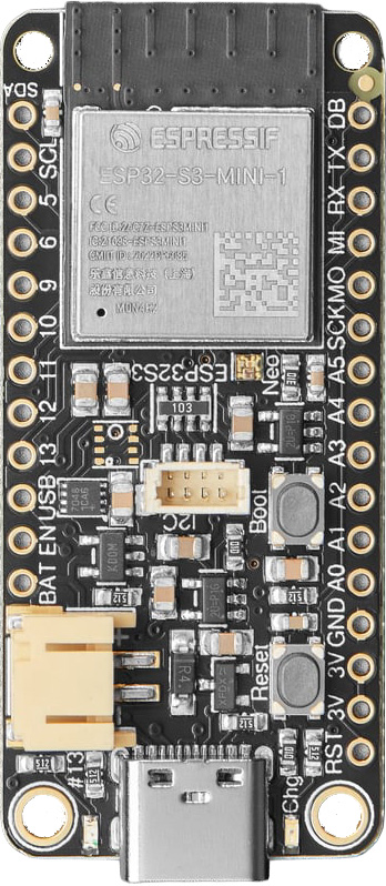 |  |  |
| Breadboard | ESP32-S3 Feather | Red LED | 220Ω Resistor |
PWM on the ESP32
To fade an LED on an Arduino Uno, you use analogWrite as we did in our LED fade lesson in our Intro to Arduino series.
Recall that analogWrite doesn’t actually drive an analog voltage to the pin. Instead, it uses pulse-width modulation (PWM). These PWM waves are produced by hardware timers that precisely drive a pin HIGH and LOW based on the set duty cycle. So, on the Arduino Uno, analogWrite(3, 127) would output a 5V value for half the period (because 127/255 ≈ 50%) on Pin 3. The Arduino Uno and Leonardo only have six PWM outputs because they have three timers, each of which can control two PWM pins.
On the ESP32, all GPIO pins support PWM, but the programming approach is different. The ESP32 uses a dedicated hardware peripheral called LEDC (LED Control) for PWM generation. The LEDC module was designed primarily for LED dimming but can also drive motors, generate tones, and produce any PWM waveform.
What about
analogWriteon the ESP32? In ESP32 Arduino core v3.x,analogWrite()is now supported as a convenience wrapper around the LEDC library (search foranalogWrite()in the esp32-hal-ledc.c source code). So you can useanalogWrite()on the ESP32, and it will work! However, we also teach the underlying LEDC API because it gives you more control over PWM frequency, resolution, and channel management—things you may for more advanced projects. And understanding the LEDC library helps you understand whatanalogWriteis doing under the hood.
The LEDC PWM library
The LEDC library provides fine-grained control over PWM output. Unlike the Arduino analogWrite (which defaults to ~490 Hz, 8-bit resolution), the LEDC library lets you choose your own PWM frequency (up to 40 MHz) and resolution (1 to 14 bits on the ESP32-S3, or up to 16 bits on the original ESP32). The Arduino version of this library is part of the core ESP32 Arduino library (esp32-hal-ledc.c), so you don’t need any #include statements to use it.
If you want to dive deeper, check out EspressIf’s LEDC guide and the LEDC source code on GitHub.
Understanding channels (the hardware)
Under the hood, the LEDC module works on channels rather than individual pins. The ESP32-S3 has 8 independent PWM channels, which means you can generate up to 8 different PWM waveforms simultaneously (each with its own frequency, resolution, and duty cycle). To apply a PWM wave to a pin, you configure a channel and then attach a pin to it. You can attach multiple pins to the exact same channel—they will all share that identical waveform—but you are limited to 8 unique waveforms running at the same time (i.e., because there are 8 independent PWM channels).
In ESP32 Arduino core v3.x, the channel abstraction was removed from the public API—you attach PWM directly to a pin with
ledcAttach(pin, freq, resolution), and the library assigns a channel automatically behind the scenes. The channels still exist in hardware, but you don’t need to manage them yourself. This is much simpler! We’ll show both the v3.x and legacy v2.x APIs below.
The LEDC API (v3.x)
In ESP32 Arduino core v3.x (which we use in this course), the LEDC API has three key methods:
/**
 * Attach a PWM channel to a pin with the specified frequency and resolution.
 * The library automatically assigns an available hardware channel.
 * Returns true on success, false if no channels are available.
 */
bool ledcAttach(uint8_t pin, uint32_t freq, uint8_t resolution);

/**
 * Write a duty cycle value to the specified pin.
 * The value should be between 0 and (2^resolution - 1).
 */
void ledcWrite(uint8_t pin, uint32_t duty);

/**
 * Detach the PWM channel from the specified pin.
 */
void ledcDetach(uint8_t pin);
Notice how much simpler this is compared to the old v2.x API (shown below for reference). You no longer need to manually manage channel numbers—just attach a pin, write a duty cycle, and you’re done!
Legacy v2.x API (click to expand)
In ESP32 Arduino core v2.x, you had to explicitly manage channels:
// Step 1: Configure a channel (0-15) with a frequency and resolution
double ledcSetup(uint8_t channel, double freq, uint8_t resolution_bits);

// Step 2: Attach a pin to that channel
void ledcAttachPin(uint8_t pin, uint8_t channel);

// Step 3: Write a duty cycle to the channel (not the pin!)
void ledcWrite(uint8_t channel, uint32_t duty);

// Detach a pin
void ledcDetachPin(uint8_t pin);
The key difference: in v2.x, ledcWrite takes a channel number. In v3.x, ledcWrite takes a pin number. If you’re following older tutorials online, this is the most common source of confusion. See the migration guide for full details.
PWM frequency and resolution tradeoff
The LEDC library lets you choose both the PWM frequency and the duty cycle resolution (in bits). But these two parameters are interdependent—you can’t max out both simultaneously. The Espressif docs provide some examples:
- A PWM frequency of 5 kHz can have a maximum duty resolution of 13 bits (\(2^{13}=8192\) discrete brightness levels, so
ledcWritevalues range from 0 to 8191) - A PWM frequency of 20 MHz can have a maximum duty resolution of 2 bits (only \(2^2=4\) discrete levels)
- A PWM frequency of 40 MHz can have a duty resolution of 1 bit—meaning the duty cycle is fixed at 50% and cannot be adjusted!
If you attempt to set incompatible frequency and resolution combinations, you’ll see an error on the Serial Monitor:
E (196) ledc: requested frequency and duty resolution cannot be achieved,
try reducing freq_hz or duty_resolution.
Why are frequency and resolution linked?
So why and how are the PWM frequency and resolution interdependent? To understand this, we need to look at how the LEDC hardware actually works.
The ESP32’s LEDC peripheral is driven by the APB clock, which runs at a fixed 80 MHz. This clock is the heartbeat that drives all the PWM timing. When you set a PWM frequency, you’re telling the LEDC hardware how long one period should be—and the clock determines how many ticks fit inside that period.
For example, at a PWM frequency of 1 MHz, each period lasts 1 µs. At 80 MHz, the clock produces 80 ticks per microsecond, so you get 80 clock ticks per period (\(80\text{ MHz} \div 1\text{ MHz} = 80\)).
Now here’s the key: resolution is about how finely you can slice up that period into distinct duty cycle levels. An \(n\)-bit resolution means you need \(2^n\) time slices. Because the hardware requires at least one clock tick per time slice, the maximum number of slices cannot exceed the total number of clock ticks available in a period.
Therefore, the fundamental rule is:
\[2^{\text{resolution}} \leq \frac{\text{APB}_{\text{clock}}}{\text{PWM}_{\text{freq}}}\]If you need more slices than you have ticks, the hardware simply can’t produce them—and ledcAttach will fail.
Here’s a visual example. The clock runs at 40 MHz, the PWM frequency is set to 1 MHz, and we show how increasing the resolution requires finer and finer time slices—which in turn demand more clock ticks:
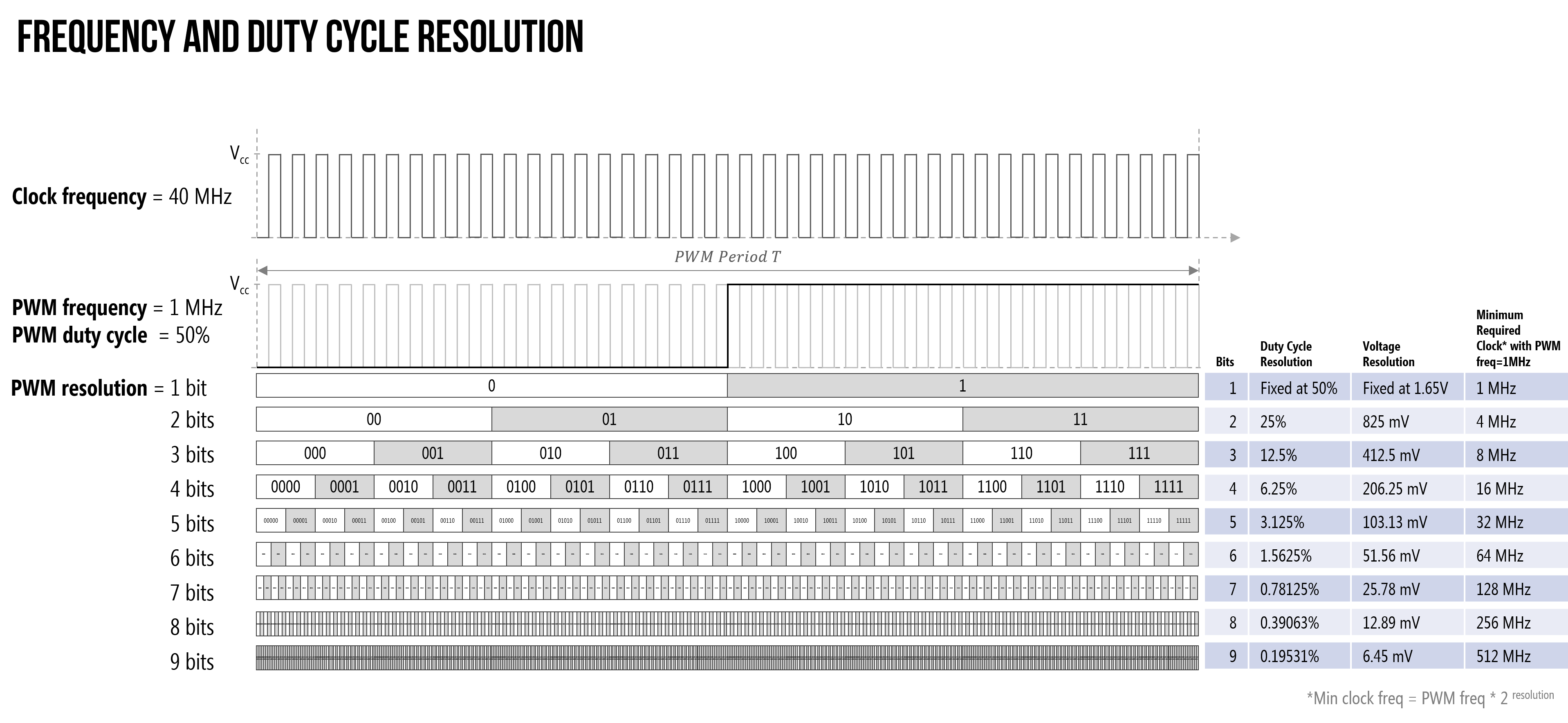 Figure. As PWM resolution increases, the number of required time slices grows exponentially. This diagram uses a simplified 40 MHz clock example—on the real ESP32 the APB clock is 80 MHz, giving you twice as many ticks to work with (and one extra bit of resolution headroom). See this PDF for a printable version.
Interactive: explore the tradeoff yourself
To advance your understanding, try the interactive visualization below. It shows a single PWM period with the 80 MHz clock ticks drawn along the top.
- Adjust the PWM Frequency slider and watch the ticks shrink (higher frequency → shorter period → fewer ticks).
- Then adjust the Resolution slider and watch the time slices multiply until they exceed the available ticks and the waveform turns red.
The insight box at the top makes the math visible: clock ticks available vs. slices needed. When slices exceed ticks, you’ll see ✗ Can’t fit—that’s the hardware telling you this combination is impossible.
Interactive Figure. Explore how PWM frequency, resolution, and duty cycle interact on the ESP32. The LEDC peripheral’s 80 MHz APB clock determines how many clock ticks fit in each PWM period. Try it: start at 1 MHz / 3 bits, then increase resolution until it breaks. Then lower the frequency and watch it become achievable again. (Open in the p5.js editor)
Why 80 MHz? The ESP32’s LEDC timers are clocked by the APB (Advanced Peripheral Bus) clock, which runs at 80 MHz. This is separate from the CPU clock (240 MHz on the ESP32-S3). The 80 MHz APB clock sets the theoretical maximum PWM frequency at 40 MHz (with 1-bit resolution: \(80 \div 2^1 = 40\)). In practice, the ESP32’s GPIO pins can’t toggle faster than about 40 MHz due to electrical switching limits, so 40 MHz at 1-bit resolution is the highest usable PWM frequency. The interactive includes 80 MHz to show the theoretical limit of the clock divider math (1 tick = 1 bit = 50% duty cycle), but you’d never use that on a real pin.
What frequency and resolution should I use?
For LED fading, you don’t need extreme values. The Arduino Uno uses ~490 Hz at 8-bit resolution, and that’s more than fast enough for smooth, flicker-free fading. A good starting point on the ESP32 is 5000 Hz at 8 bits—comfortably within the clock’s capability, with 256 brightness levels. Feel free to experiment!
Alternatives to LEDC
In addition to the LEDC module, the ESP32 supports other analog output options. We won’t use these alternatives in this course, but they’re worth knowing about if you explore audio or precision analog output projects in the future.
-
Sigma-delta modulation (docs): Uses a feedback loop to minimize timer errors and produce more accurate waveforms than PWM. There is a sigma-delta example in the Arduino IDE: File → Examples → ESP32 → AnalogOut → SigmaDelta.
-
DAC (original ESP32 only): The original ESP32 has two 8-bit digital-to-analog converter channels on GPIO25 and GPIO26, which can output true analog voltages (not PWM!). This enables smooth sinusoidal waveforms and audio output. There are many examples online of using the ESP32’s DAC to play music—see this tutorial by Xtronical.
The ESP32-S3 does not have a DAC. If you need true analog output on the ESP32-S3, you’ll need an external DAC module (like the MCP4725) connected via I2C, or you can use PWM with a low-pass RC filter to approximate an analog voltage.
Let’s make an ESP32-based LED fader!
Let’s put it all together and fade an LED.
The circuit
We can use the same circuit as the Blink lesson:
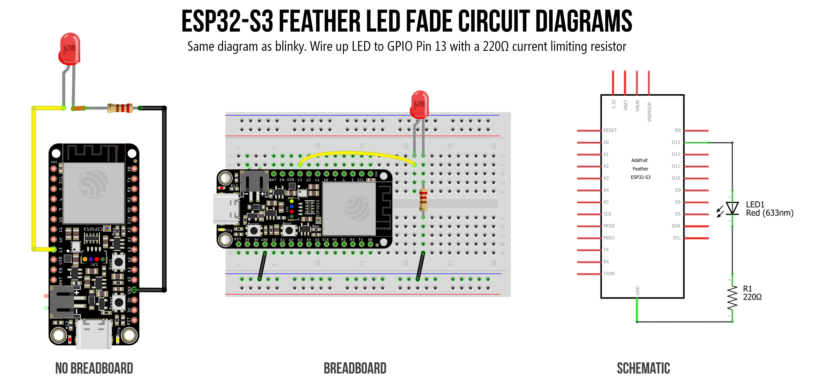 Figure. Same circuit as the Blink lesson. On the ESP32-S3 Feather, we’re using GPIO 13 (but you can use any output-capable pin, just change the
 LED_OUTPUT_PIN in the code).
The code (v3.x API)
We’ll walk through the code step by step. You may also want to check out the official ESP32 fade example in the Arduino IDE: File → Examples → ESP32 → AnalogOut → LEDCSoftwareFade (source on GitHub).
Step 1: Set up the PWM and pin constants
const int LED_OUTPUT_PIN = 13;  // GPIO 13 = LED_BUILTIN on ESP32-S3 Feather and Huzzah32
                                // Change to match your wiring if using a different pin

const int PWM_FREQ = 5000;     // 5 kHz PWM frequency (Arduino Uno uses ~490 Hz)
const int PWM_RESOLUTION = 8;  // Set to 8-bit resolution (0-255), same as Arduino Uno
                               // ESP32-S3 supports up to 14-bit resolution

// The max duty cycle value based on PWM resolution (255 for 8 bits)
const int MAX_DUTY_CYCLE = (1 << PWM_RESOLUTION) - 1;

const int DELAY_MS = 4;        // delay between fade increments
Step 2: Attach PWM to the pin in setup()
In v3.x, this is a single call—no separate channel setup required:
void setup() {
  Serial.begin(115200);

  // Attach a PWM channel to the pin with the specified frequency and resolution.
  // The library automatically assigns an available hardware channel.
  ledcAttach(LED_OUTPUT_PIN, PWM_FREQ, PWM_RESOLUTION);
}
Compare this to the v2.x approach, which required two separate calls:
// v2.x (legacy) — DON'T use this with ESP32 Arduino core v3.x!
// ledcSetup(PWM_CHANNEL, PWM_FREQ, PWM_RESOLUTION);
// ledcAttachPin(LED_OUTPUT_PIN, PWM_CHANNEL);
Step 3: Write the fade loop()
The fade loop is similar to the original Arduino LED fade lesson. Instead of analogWrite(pin, value), we use ledcWrite(pin, value):
void loop() {
  // Fade up: ramp duty cycle from 0% (off) to 100% (full brightness)
  for (int dutyCycle = 0; dutyCycle <= MAX_DUTY_CYCLE; dutyCycle++) {
    ledcWrite(LED_OUTPUT_PIN, dutyCycle);
    delay(DELAY_MS);
  }

  // Fade down: ramp duty cycle from 100% back to 0% (off)
  for (int dutyCycle = MAX_DUTY_CYCLE; dutyCycle >= 0; dutyCycle--) {
    ledcWrite(LED_OUTPUT_PIN, dutyCycle);
    delay(DELAY_MS);
  }
}
In v3.x,
ledcWritetakes a pin number. In the old v2.x API, it took a channel number. If you’re following older tutorials online and your LED doesn’t fade, this is probably why!
Step 4: Run it!
That’s it—upload and run! You should see your LED smoothly fade on and off. Try experimenting with different PWM_FREQ and PWM_RESOLUTION values to see the tradeoff in action.
Full source code
Here’s the complete program. This source code is also on GitHub (note: the GitHub version may still use the v2.x API).
/**
 * Fades an LED on and off using the ESP32 LEDC PWM library.
 *
 * Uses the v3.x LEDC API (ledcAttach / ledcWrite with pin numbers).
 * If you're using ESP32 Arduino core v2.x, see the legacy API in the lesson.
 *
 * See: https://makeabilitylab.github.io/physcomp/esp32/led-fade
 * Source: https://github.com/makeabilitylab/arduino/blob/master/ESP32/Basics/Fade/Fade.ino
 */

const int LED_OUTPUT_PIN = 13;  // GPIO 13
const int PWM_FREQ = 5000;      // 5 kHz — fast enough to avoid visible flicker
const int PWM_RESOLUTION = 8;   // 8-bit resolution: duty cycle ranges from 0 to 255
const int MAX_DUTY_CYCLE = (1 << PWM_RESOLUTION) - 1;  // 2^8 - 1 = 255

const int DELAY_MS = 4;         // Small delay between steps for a smooth ~1-second fade

void setup() {
  Serial.begin(115200);

  // Attach a PWM channel to the pin with the specified frequency and resolution.
  // The library automatically assigns an available hardware channel.
  ledcAttach(LED_OUTPUT_PIN, PWM_FREQ, PWM_RESOLUTION);
}

void loop() {
  // Fade up: ramp duty cycle from 0% (off) to 100% (full brightness)
  for (int dutyCycle = 0; dutyCycle <= MAX_DUTY_CYCLE; dutyCycle++) {
    ledcWrite(LED_OUTPUT_PIN, dutyCycle);
    Serial.print("Duty cycle: ");
    Serial.println(dutyCycle);
    delay(DELAY_MS);
  }

  // Fade down: ramp duty cycle from 100% back to 0% (off)
  for (int dutyCycle = MAX_DUTY_CYCLE; dutyCycle >= 0; dutyCycle--) {
    ledcWrite(LED_OUTPUT_PIN, dutyCycle);
    Serial.print("Duty cycle: ");
    Serial.println(dutyCycle);
    delay(DELAY_MS);
  }
}
Legacy v2.x version of this code (click to expand)
If you’re using ESP32 Arduino core v2.x, the code uses explicit channel management:
const int PWM_CHANNEL = 0;     // ESP32 has 16 channels (0-15) for independent waveforms
const int PWM_FREQ = 5000;
const int PWM_RESOLUTION = 8;
const int MAX_DUTY_CYCLE = (1 << PWM_RESOLUTION) - 1;

const int LED_OUTPUT_PIN = 21;  // GPIO 21 on Huzzah32
const int DELAY_MS = 4;

void setup() {
  // Step 1: Configure channel 0 with frequency and resolution
  ledcSetup(PWM_CHANNEL, PWM_FREQ, PWM_RESOLUTION);

  // Step 2: Attach pin to that channel
  ledcAttachPin(LED_OUTPUT_PIN, PWM_CHANNEL);
}

void loop() {
  // Note: ledcWrite takes a CHANNEL number in v2.x, not a pin!
  for (int dutyCycle = 0; dutyCycle <= MAX_DUTY_CYCLE; dutyCycle++) {
    ledcWrite(PWM_CHANNEL, dutyCycle);
    delay(DELAY_MS);
  }

  for (int dutyCycle = MAX_DUTY_CYCLE; dutyCycle >= 0; dutyCycle--) {
    ledcWrite(PWM_CHANNEL, dutyCycle);
    delay(DELAY_MS);
  }
}
Workbench video
Video. A workbench video of fading an external LED on the Adafruit ESP32-S3.
Try it in Wokwi
You can also run this circuit in the Wokwi simulator (introduced in the Blink lesson). Wokwi uses the ESP32-S3 DevKitC board but since the LEDC library works the same on any ESP32-S3 board, the fade code runs identically in the simulator as it would on the ESP32-S3 Feather.
Video. LED fade running in the Wokwi simulator on the ESP32-S3 DevKitC. Run it yourself on Wokwi here.
→ Open the Fade simulation in Wokwi
Using analogWrite instead
Since ESP32 Arduino core v3.x supports analogWrite as a wrapper around the LEDC library, you can write the same fade with much less code. Under the hood, analogWrite calls ledcAttach and ledcWrite for you, using defaults of 1 kHz and 8-bit resolution.
/**
 * Fades an LED on and off using analogWrite().
 *
 * On ESP32 Arduino core v3.x, analogWrite() is a convenience wrapper
 * around the LEDC library. It defaults to 1 kHz PWM at 8-bit resolution.
 * This is the simplest way to fade an LED—identical to Arduino Uno code!
 *
 * See: https://makeabilitylab.github.io/physcomp/esp32/led-fade
 */

const int LED_OUTPUT_PIN = 13;  // GPIO 13 = LED_BUILTIN on ESP32-S3 Feather
const int DELAY_MS = 4;         // Small delay between steps for a smooth fade

void setup() {
  // Set the LED output pin
  pinMode(LED_OUTPUT_PIN, OUTPUT);
}

void loop() {
  // Fade up: ramp from 0 (off) to 255 (full brightness)
  for (int brightness = 0; brightness <= 255; brightness++) {
    analogWrite(LED_OUTPUT_PIN, brightness);
    delay(DELAY_MS);
  }

  // Fade down: ramp from 255 back to 0
  for (int brightness = 255; brightness >= 0; brightness--) {
    analogWrite(LED_OUTPUT_PIN, brightness);
    delay(DELAY_MS);
  }
}
Look familiar? This code is identical to what you’d write on an Arduino Uno—that’s the whole point of the analogWrite wrapper. The tradeoff is that you lose control over PWM frequency and resolution (stuck at 1 kHz / 8-bit defaults). You can change these defaults with analogWriteFrequency(pin, freq) and analogWriteResolution(pin, bits), but at that point you might as well use the LEDC API directly.
You can play with the above LED fade analogWrite example on Wokwi here.
Now that you know about both the LEDC and the
analogWriteapproach to driving PWM signals on the ESP32 GPIO pins, you should decide which is better for you and your program!
Bonus: Fade the NeoPixel through the rainbow 🌈
In Lesson 2, we blinked the onboard NeoPixel in discrete colors using both the built-in rgbLedWrite() function as well as via the external Adafruit_NeoPixel.h library. Now let’s smoothly fade through the entire color wheel using the HSV color space—the same approach we used in the Addressable LEDs lesson.
Because the Adafruit NeoPixel library supports ColorHSV(), which makes it easier to cross-fade across colors, we’ll use that library again here. The ColorHSV() function takes a 16-bit hue (0–65535 maps to 0°–360°), a saturation (0–255), and a value/brightness (0–255). By incrementing the hue each frame, we get a smooth rainbow cross-fade:
/**
 * Smoothly fades the onboard NeoPixel through the full HSV color wheel.
 * Works on the Adafruit ESP32-S3 Feather (and in Wokwi with the DevKitC).
 *
 * Requires the Adafruit NeoPixel library:
 *   Sketch -> Include Library -> Manage Libraries -> search "Adafruit NeoPixel"
 *
 * See: https://makeabilitylab.github.io/physcomp/esp32/led-fade
 */
#include <Adafruit_NeoPixel.h>

// One NeoPixel on the board, on the pin defined by PIN_NEOPIXEL
Adafruit_NeoPixel _pixel(1, PIN_NEOPIXEL, NEO_GRB + NEO_KHZ800);

const int HUE_STEP = 256;             // How much to advance the hue each frame
const uint32_t MAX_HUE = 65536;       // Full color wheel (360°) in 16-bit hue
const int DELAY_MS = 20;              // ~50 fps for smooth animation

uint32_t _hue = 0;                    // Current position on the color wheel

void setup() {
  // The NeoPixel on the ESP32-S3 Feather has a separate power pin
  // that must be set HIGH before the NeoPixel will light up
  #if defined(NEOPIXEL_POWER)
    pinMode(NEOPIXEL_POWER, OUTPUT);
    digitalWrite(NEOPIXEL_POWER, HIGH);
  #endif

  _pixel.begin();
  _pixel.setBrightness(30);  // 0-255; keep it low to avoid blinding yourself!
  _pixel.show();
}

void loop() {
  // ColorHSV takes: hue (0-65535), saturation (0-255), value/brightness (0-255)
  // gamma32 applies perceptual brightness correction for
  // smoother color transitions
  uint32_t color = _pixel.gamma32(_pixel.ColorHSV(_hue, 255, 255));
  _pixel.setPixelColor(0, color);
  _pixel.show();

  // Advance the hue and wrap around at 65536 (back to red)
  _hue = (_hue + HUE_STEP) % MAX_HUE;

  delay(DELAY_MS);
}
Upload this and watch your NeoPixel smoothly cycle through the rainbow and back to red! Try changing HUE_STEP to 64 (slower, more gradual) or 1024 (faster cycling).
We also built a version on Wokwi, which you can simulate here.
What is
gamma32()? Human eyes don’t perceive brightness linearly—we’re much more sensitive to changes in dark tones than bright ones. Thegamma32()function applies a correction curve so that the color transitions look smooth and even, rather than appearing to jump through the midrange. Compare the output with and withoutgamma32()to see the difference! We cover this in more detail in the Addressable LEDs lesson.
HSV vs. RGB: In the RGB color model, creating a smooth rainbow requires manually calculating red, green, and blue values for each hue—which is tedious and error-prone. The HSV (Hue, Saturation, Value) model separates color from brightness, so sweeping through all colors is just a matter of incrementing one number (the hue). We use HSV extensively in the Addressable LEDs lesson and also talk about it in the RGB LED lesson.
Using the Huzzah32 instead? (click to expand)
The original Huzzah32 does not have an onboard NeoPixel. If you want to try this, you’ll need to connect an external NeoPixel (or NeoPixel strip) to a GPIO pin and update PIN_NEOPIXEL to match your wiring. See our Addressable LEDs lesson for details on wiring external NeoPixels.
Workbench video of RGB crossfade
Video. A workbench video cross fading the built-in RGB LED on the Adafruit ESP32-S3 across colors.
Summary
In this lesson, you learned how to fade an LED on the ESP32 using the LEDC PWM library. The key takeaways:
- The ESP32 uses the LEDC (LED Control) hardware peripheral for PWM, which offers more control than Arduino’s
analogWrite(thoughanalogWriteis now supported on the ESP32 as a convenience wrapper in v3.x). - In v3.x, PWM setup is simple:
ledcAttach(pin, freq, resolution)to configure,ledcWrite(pin, duty)to set the duty cycle. - PWM frequency and resolution are interdependent—higher resolution requires a proportionally faster clock. For LED fading, 5 kHz at 8-bit resolution is a good default.
- The ESP32-S3 does not have a DAC for true analog output (the original ESP32 does). Use PWM or an external DAC.
- For simple fades,
analogWrite()works on the ESP32 in v3.x with no setup—but you give up control over frequency and resolution. - The onboard NeoPixel can be smoothly faded through the color wheel using HSV color and
gamma32()for perceptually smooth transitions.
Exercises
Exercise 1: Change the PWM resolution to 12 bits. What is the new maximum duty cycle value? Update MAX_DUTY_CYCLE and verify the fade still works smoothly. Do you notice any difference in the smoothness of the fade compared to 8 bits?
Exercise 2: Try setting the PWM frequency to 100 Hz with 8-bit resolution. Can you see the LED flickering? At what frequency does the flickering become invisible to your eye? (Hint: try 200 Hz, 500 Hz, 1000 Hz.)
Exercise 3: Compare the analogWrite version (shown above) to the LEDC version. What PWM frequency and resolution does analogWrite use by default? Can you change them? (Hint: check the Arduino-ESP32 docs for analogWriteFrequency and analogWriteResolution.)
Exercise 4: Connect two LEDs to different GPIO pins and make them fade in opposite directions—when one is bright, the other is dim, and vice versa.
Exercise 5: Using the formula \(2^{resolution} \leq \frac{80{,}000{,}000}{PWM_freq}\), calculate the maximum resolution (in bits) you can use at 10 kHz. What about at 1 MHz? Check your answers with the interactive visualization above.
Next Lesson
In the next lesson, we’ll use a potentiometer to control an LED’s brightness and learn about the ESP32’s analog input.