Lesson 7: RGB LEDs
Table of Contents
- Materials
- Common Cathode
- Common Anode
- Coding for both Common Cathode and Anode
- Lesson Summary
- Next Lesson
In this tutorial, we will use an RGB LED (RGB stands for Red, Green, Blue) to flash through a sequence of colors and learn about the difference between a Common Anode and Common Cathode RGB LED design.
Materials
You’ll need the following materials. Importantly, there are two types of RGB LEDs—described below—so make sure you determine which type of RGB LED you are using as it will affect how you configure your circuit. But don’t worry, we’ll walk through both RGB LED types.
| Breadboard | Arduino | RGB LED | Resistors |
|---|---|---|---|
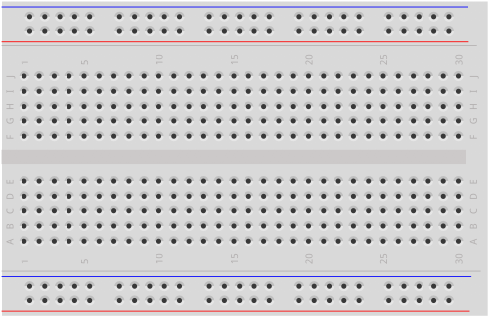 | 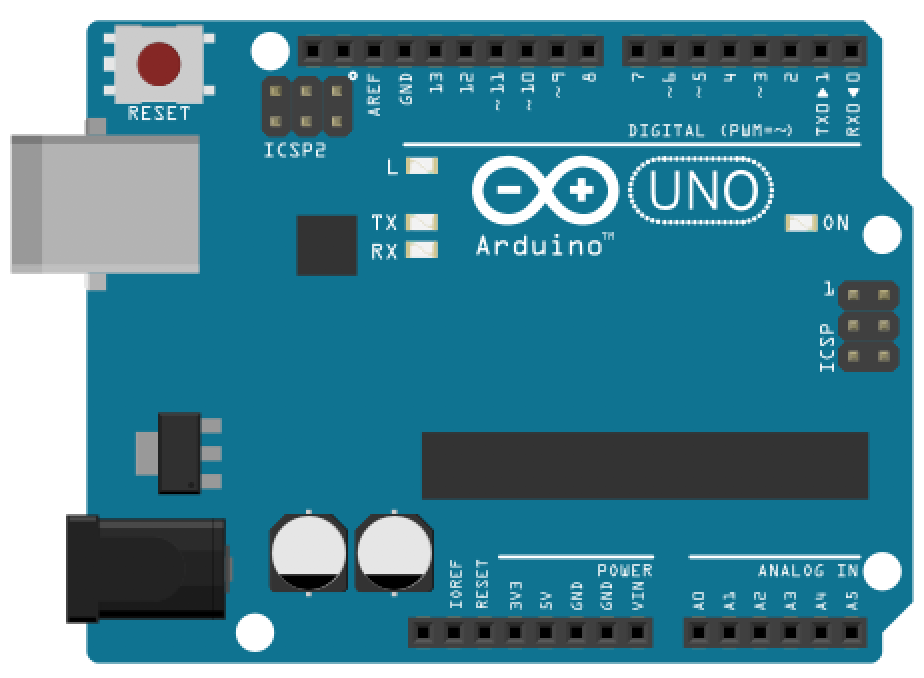 | 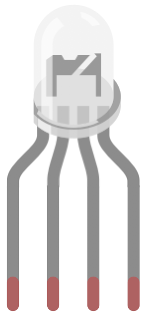 |  |
| Breadboard | Arduino Uno, Leonardo, or similar | RGB LED (Either Common Cathode or Common Anode) | Three 220Ω Resistors |
Common Anode vs. Common Cathode
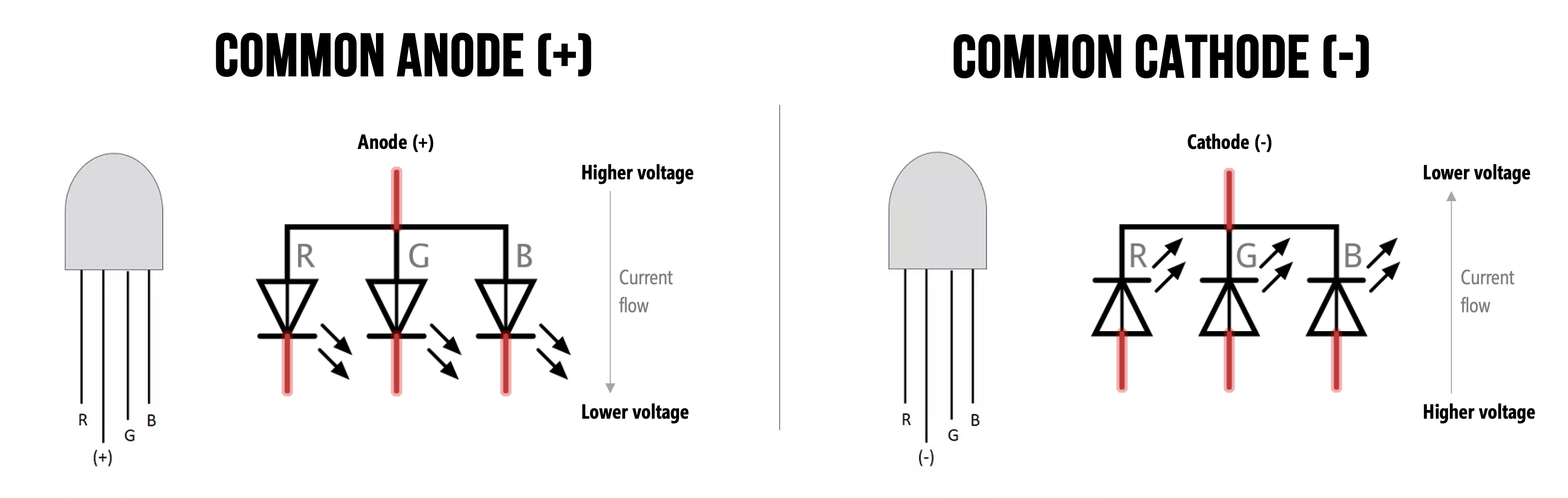
While capable of displaying thousands of color combinations, RGB LEDs are actually quite simple; they contain three separate LEDs in one package: red, green, and blue. Importantly but somewhat confusingly, there are two RGB LED designs—the Common Anode and the Common Cathode—which differ in the leg shared between the three embedded LEDs.
- With the Common Anode, the three embedded LEDs share the anode leg. To control the RGB LED’s color, you must hook up the anode to the higher voltage source and connect the red, green, and blue legs to lower voltage levels (e.g., ground). For example, with a 5V voltage source connected to the common anode leg, setting the three other legs (red, green, blue) to 5V would, somewhat counterintuively, turn off the LED.
- In contrast, the Common Cathode works much more like a typical LED (e.g., like the red LED from our previous lessons). Here, all three embedded LEDs share the cathode leg. So, you drive each individual color leg with a higher voltage source.
How can I tell if I have a Common Anode or Cathode RGB LED?
You cannot tell whether you have a Common Anode or Common Cathode RGB LED by visual inspection. Instead, consult the supplier website, the datasheet, or experiment with the LED yourself (remember, diodes only work in one direction so as long as you include your current limiting resistors, you should be fine!).
| Common Anode | Common Cathode |
|---|---|
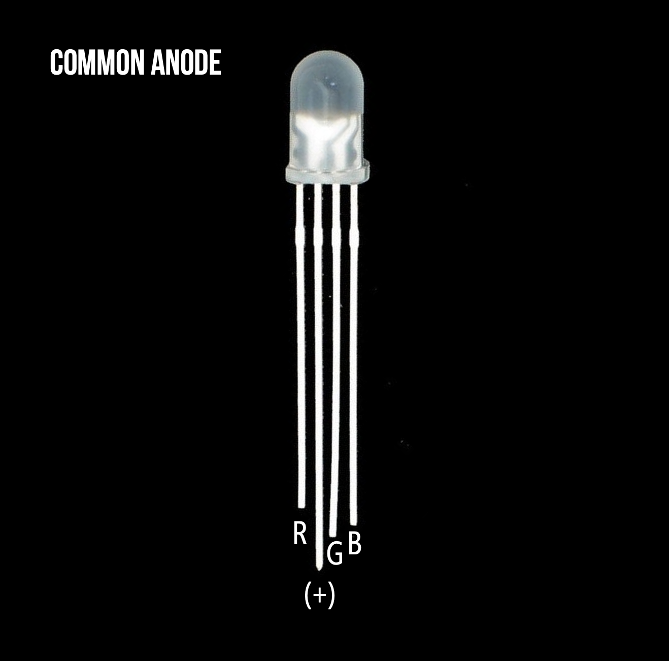 | 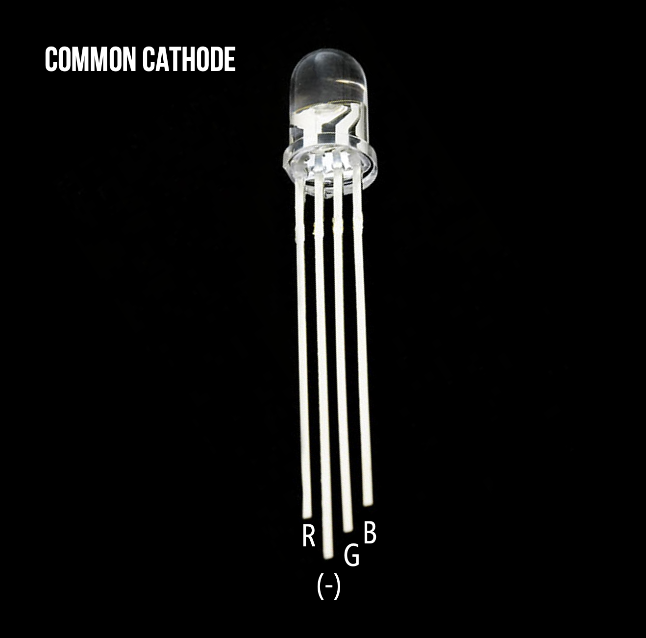 |
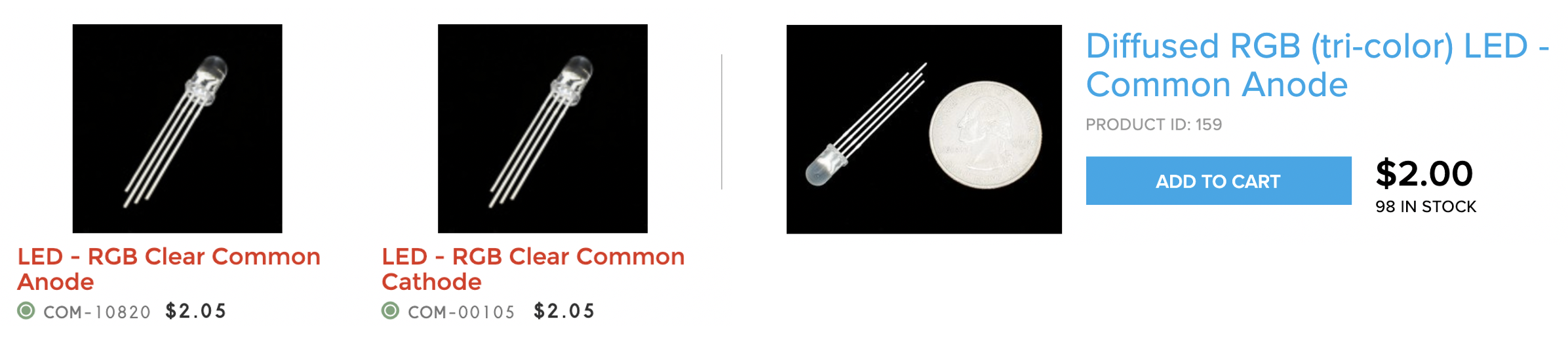
| A diffused Common Anode RGB LED from Adafruit. It’s called diffused because the epoxy casing is scratchy and not perfectly transparent | A clear Common Cathode RGB LED from Sparkfun. |
Here are two screenshots of supplier websites (Sparkfun and Adafruit). Notice how the RGB LED type is clearly labeled.
Common Cathode
We’re going to start with a Common Cathode circuit + code because it’s more intuitive (and similar to our red LED tutorials) before covering the Common Anode version.
Making the circuit
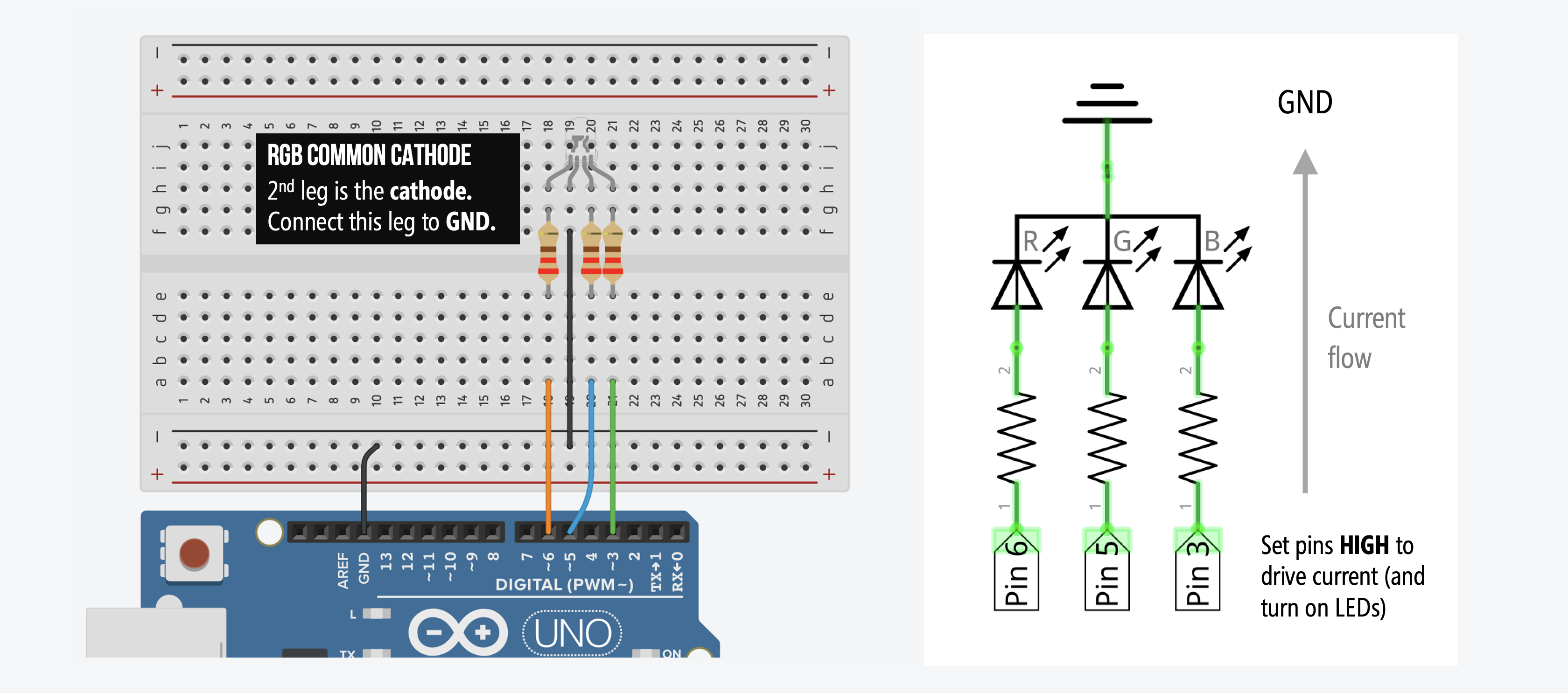
With a Common Cathode design, the 2nd leg needs to be hooked up to the GND pin and the 1st (red), 3rd (blue), and 4th (green) legs should connect to digital I/O pins (don’t forget a current limiting resistor for each). We could have used any digital I/O pins; however, we chose Pins 6, 5, and 3 for red, blue, and green respectively (these pins support PWM and thus, we’ll be able to use the same circuit for our next tutorial on cross-fading colors with RGB LEDs).
Here’s the wiring without a breadboard (not recommended but perhaps easier to see the circuit itself):

And here’s the wiring with a breadboard (the schematic on the right is the same either way). Notice how the schematic highlights how the current flows from the I/O pins, through the resistors, into the RGB LED, and then down to ground.
Writing the code
We are going to write code that flashes through a sequence of colors. Recall that the embedded red LED is hooked up to Pin 6, the blue LED to Pin 5, and the green LED to Pin 3. We will control the RGB LED color by outputting HIGH (5V) or LOW (0V) using digitalWrite to these pins.
For example, to make the RGB LED turn red, we would write:
digitalWrite(RGB_RED_LED_PIN, HIGH);
digitalWrite(RGB_GREEN_LED_PIN, LOW);
digitalWrite(RGB_BLUE_LED_PIN, LOW);
Similarly, to make the RGB LED turn green, we would write:
digitalWrite(RGB_RED_LED_PIN, LOW);
digitalWrite(RGB_GREEN_LED_PIN, HIGH);
digitalWrite(RGB_BLUE_LED_PIN, LOW);
In this example, we will flash the following sequence:
| Color | Red, Green, Blue Pin Values |
|---|---|
| Red | HIGH, LOW, LOW |
| Green | LOW, HIGH, LOW |
| Blue | LOW, LOW, HIGH |
| Purple | HIGH, LOW, HIGH |
| Turqoise | LOW, HIGH, HIGH |
| White | HIGH, HIGH, HIGH |
NOTE: For those familiar with html, this is very similar to html hexadecimal color codes where red, for example, is specified by #FF0000, green by #00FF00, blue by #0000FF, and so on.
Step 1: Write initialization code
As usual, we introduce some constants for our literal assignments and then setup our pins as OUTPUT.
const int DELAY_MS = 1000;       // delay between color changes in ms
const int RGB_RED_LED_PIN = 6;   // indicated by orange wire
const int RGB_GREEN_LED_PIN = 5; // indicated by green wire
const int RGB_BLUE_LED_PIN = 3;  // indicated by blue wire

void setup()
{
  // Set the red, green, and blue RGB LED pins to output
  pinMode(RGB_RED_LED_PIN, OUTPUT);
  pinMode(RGB_BLUE_LED_PIN, OUTPUT);
  pinMode(RGB_GREEN_LED_PIN, OUTPUT);
}
Step 2: Write a new helper function called setRgbLedColor
To help set RGB LED colors, we are going to write a new function called setRgbLedColor(int red, int green, int blue), which takes in either a HIGH or LOW for the red, green, and blue int parameters.
// Function expects either HIGH or LOW for each parameter
void setRgbLedColor(int red, int green, int blue){
  digitalWrite(RGB_RED_LED_PIN, red);
  digitalWrite(RGB_GREEN_LED_PIN, green);
  digitalWrite(RGB_BLUE_LED_PIN, blue);
}
Step 3: Write the color sequence
Now, in loop(), we’ll write the specific color sequence that we want:
void loop()
{
  // red
  setRgbLedColor(HIGH, LOW, LOW);
  delay(DELAY_MS);

  // green
  setRgbLedColor(LOW, HIGH, LOW);
  delay(DELAY_MS);

  // blue
  setRgbLedColor(LOW, LOW, HIGH);
  delay(DELAY_MS);

  // purple
  setRgbLedColor(HIGH, LOW, HIGH);
  delay(DELAY_MS);

  // turqoise
  setRgbLedColor(LOW, HIGH, HIGH);
  delay(DELAY_MS);

  // white
  setRgbLedColor(HIGH, HIGH, HIGH);
  delay(DELAY_MS);
}
Step 4: Compile, upload, and run
That’s it. Now compile, upload, and run your code!
In the video below, I’m running our BlinkRGB code, which is the same as above but includes some Serial.print calls for debugging (see this mini-tutorial on using the Serial.print and the Arduino IDE’s Serial Monitor for debugging)
The yogurt container is used to diffuse the light. Kleenex, white paper, or a ping pong ball (with a hole in it for the LED) works well too!
Below, we show a video animation of the code executing and resulting circuit behavior. Pay close attention to the direction of current—it will flow in the opposite direction with the Common Anode design (covered next).
Common Anode
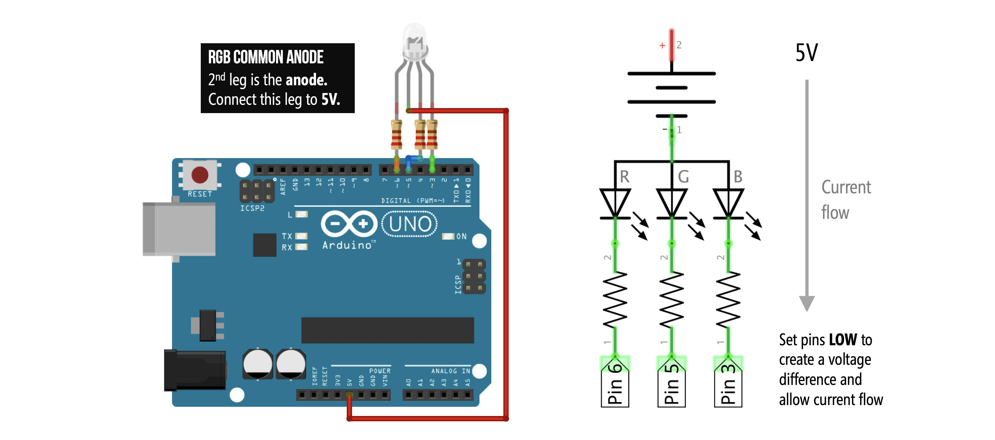
Now, let’s work on the Common Anode version. The circuit wiring is almost the exact same as before: the 1st leg (red), 3rd leg (blue), and 4th leg (green) of the RGB LED connect to digital I/O Pins 6, 5, and 3 respectively (along with a current limiting resistor for each); however, the 2nd leg is now a common anode and thus, should be connected to 5V (and not GND as it was for the common cathode).
To drive current through our circuit and turn on an embedded LED—say the red LED—we counterintuitively have to set the corresponding red LED pin to LOW (Pin 6, in this case) and the other LED pins to HIGH (Pins 5 and 3). Why? Remember that current always flows from high potential to low potential. With a Common Anode, the 2nd leg is the anode (high potential or, in this case, 5V) so we must connect the other legs to lower potential to create a voltage difference and allow current to flow.
Note: Does this setup seem familiar? It should. With the Common Anode RGB LED, the digital I/O pins become current sinks just like LED Circuit 2 in the LED Blink 2 tutorial.
Making the circuit
As before, here’s a circuit wiring diagram without a breadboard (which more cleanly shows connections but would be difficult, in practice, to reliably make):
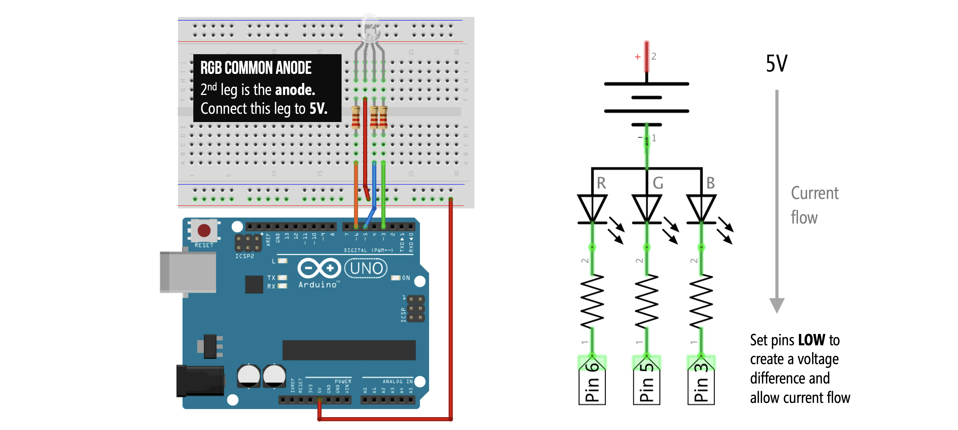
And here’s the more practical breadboarded version (again, the circuit diagram is the same in both the non-breadboard and breadboard version):
Writing the code
The Common Anode RGB LED works opposite to the Common Cathode version—to turn on a particular color, we write out LOW rather than HIGH. For example, to make the RGB LED turn red, we would write:
digitalWrite(RGB_RED_LED_PIN, LOW);
digitalWrite(RGB_GREEN_LED_PIN, HIGH);
digitalWrite(RGB_BLUE_LED_PIN, HIGH);
Similarly, to make the RGB LED turn green, we would write:
digitalWrite(RGB_RED_LED_PIN, HIGH);
digitalWrite(RGB_GREEN_LED_PIN, LOW);
digitalWrite(RGB_BLUE_LED_PIN, HIGH);
We will flash the same sequence as before but again our HIGHs and LOWs are flipped:
| Color | Red, Green, Blue Pin Values |
|---|---|
| Red | LOW, HIGH, HIGH |
| Green | HIGH, LOW, HIGH |
| Blue | HIGH, HIGH, LOW |
| Purple | LOW, HIGH, LOW |
| Turqoise | HIGH, LOW, LOW |
| White | LOW, LOW, LOW |
Here’s an animation. Pay close attention to the current direction—it flows from 5V down through the LED, the current limiting resistors, and into the digital I/O pins.
We’re not going to include code specifically for the Common Anode RGB LED. Instead, we’ll show how to adapt our previous Common Cathode code with only a few additional lines.
Coding for both Common Cathode and Anode
Because the only difference between the Common Cathode code and the Common Anode code is inverting HIGHs and LOWs, we can simply update our previous Common Cathode code by adding in a boolean to check for which RGB LED version we are using. If a Common Anode then we will invert the HIGH and LOW signals—see the setRgbLedColor function. The full code is on GitHub and shown below:
This source code is on GitHub.
Lesson Summary
In this lesson, you added color to your output capabilities! You learned:
- That an RGB LED actually contains three separate microscopic LEDs (Red, Green, Blue) in one package.
- The critical difference between Common Cathode (shares a ground leg) and Common Anode (shares a 5V supply leg) components.
- How to wire and write code for a Common Cathode RGB LED (driving pins
HIGHto turn on colors). - How to adapt code for a Common Anode RGB LED using your knowledge of current sinking (driving pins
LOWto turn on colors).
Next Lesson
In the next lesson, we will learn how to fade between RGB colors and how to convert to the HSL colorspace to more easily (and independently) control hue and brightness.