Lesson 6: Blinking Two LEDs
Table of Contents
- Materials
- Before you begin: breadboarding circuits
- Making the circuit
- Writing the code: blinking Pins 3 and 4
- Our Blink2 code on GitHub
- Exercises
- Lesson Summary
- Next Lesson
In this tutorial, we will learn the difference between current sourcing and current sinking by revisiting our LED Blink example. We will also incorporate the use of a breadboard.
We are going to build two simple LED circuits:
- LED Circuit 1 will be the exact same as before with the LED anode facing Pin 3 and the cathode facing ground. When we drive Pin 3
HIGH(5V), the current will travel through the LED toGND. In this circuit, Pin 3 is the current source. - LED Circuit 2 is similar but different. Here, we’ll hook up a second LED with the anode facing away from Pin 4 (instead, towards 5V) and the cathode facing toward Pin 4. When we drive Pin 4
HIGH(5V), the LED will turn off because no voltage difference exists between the two ends of our circuit. However, if we drive Pin 4LOW(0V), the LED will turn on. In this circuit, Pin 4 is the current sink.
Yes, this can be a bit confusing at first (“wait, the LED turns off when Pin 4 is HIGH?!?!”). But you’ll gain understanding by completing this lesson. In the animation below, pay attention to the current direction in each circuit. Notice how they’re opposite!
Materials
Our materials are almost the same as before but this time, we are going to make two separate LED circuits (with the same components). So, we need two red LEDs and two 220Ω resistors. Now that we’re using more components, we’ll also need a breadboard—which will make it easier to make a clean, organized circuit.
| Breadboard | Arduino | LED | Resistor |
|---|---|---|---|
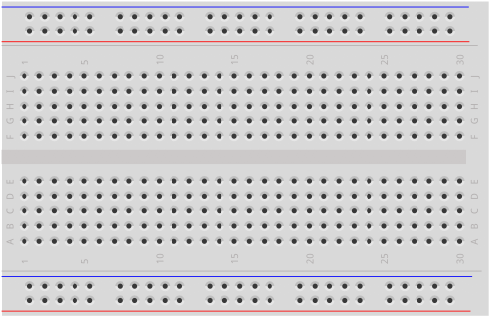 | 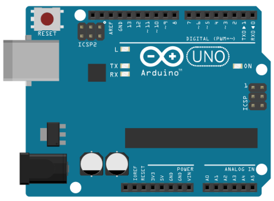 | 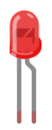 | 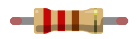 |
| Breadboard | Arduino Uno, Leonardo, or similar | 2 Red LEDs | 2 220Ω Resistors |
Before you begin: breadboarding circuits
We will increasingly be using our breadboards in these lessons so now is a good opportunity to revisit how to use them. If you’re unfamiliar please read our breadboarding guide and watch the following video:
Making the circuit
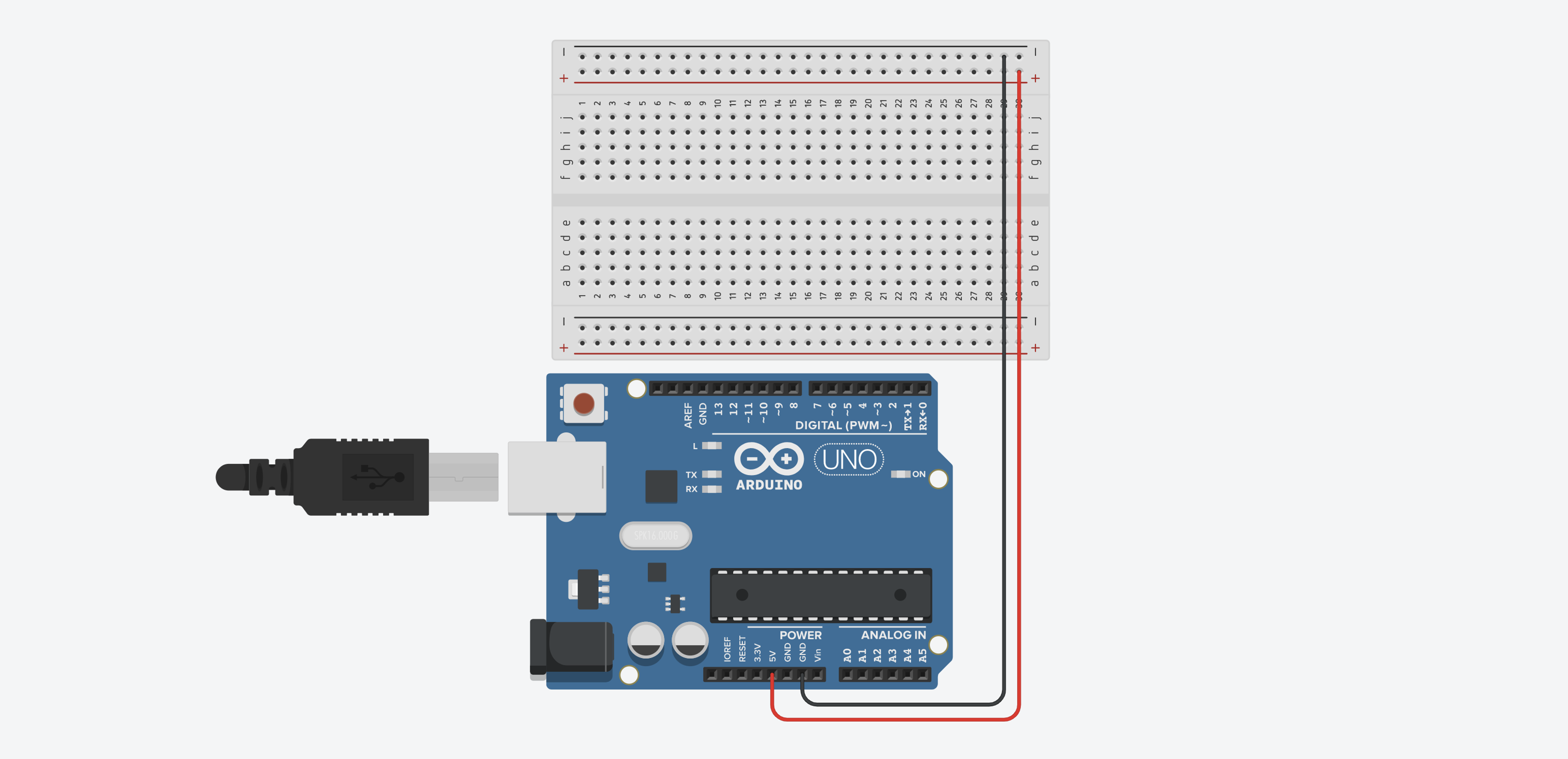
Step 1: Wire up the power and GND rails
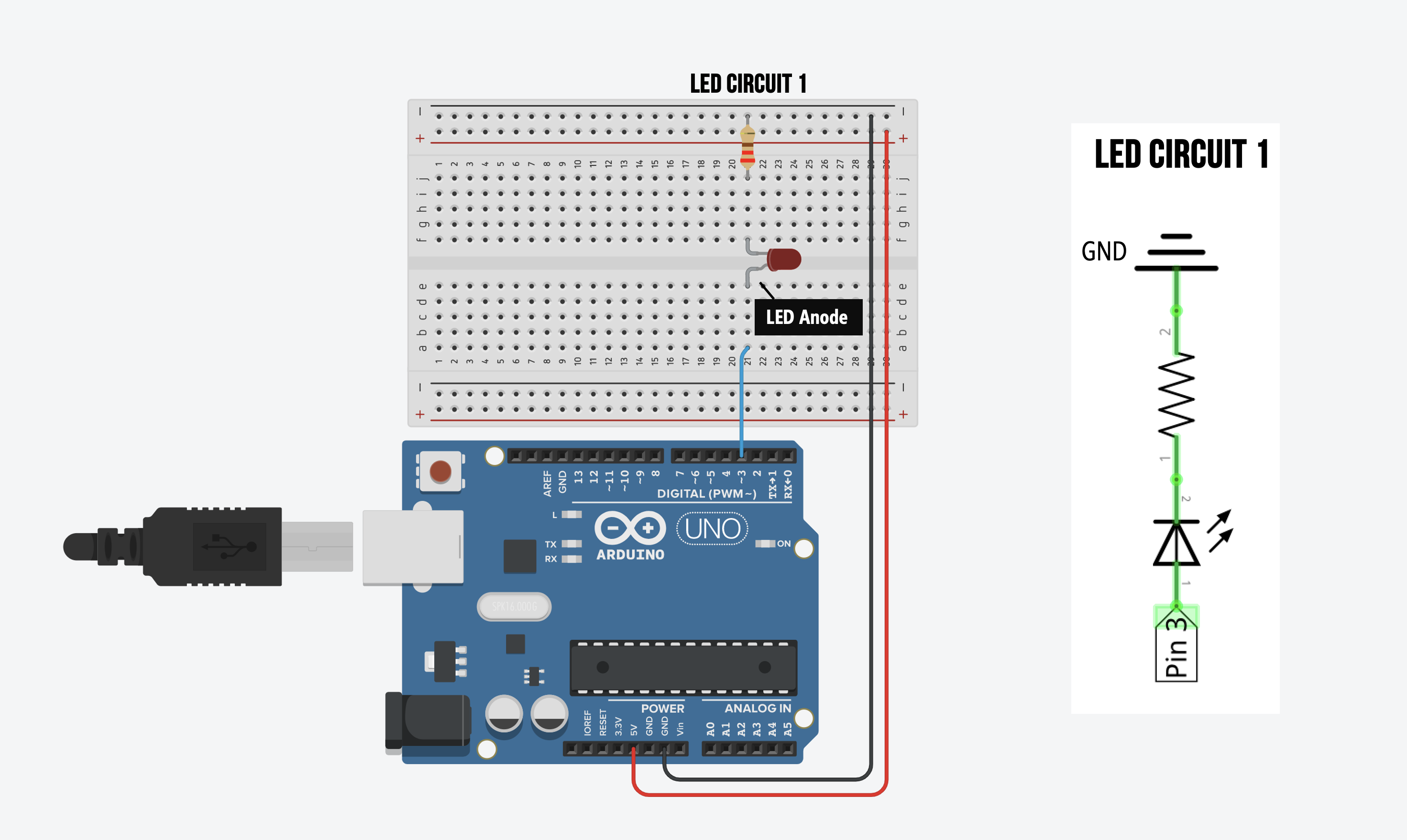
Step 2: Wire up the first LED circuit
Now let’s wire up the exact same circuit as before (e.g., LED Blink and LED Fade) but this time we’ll use a breadboard. Make sure the LED anode (the long leg) is facing Pin 3.
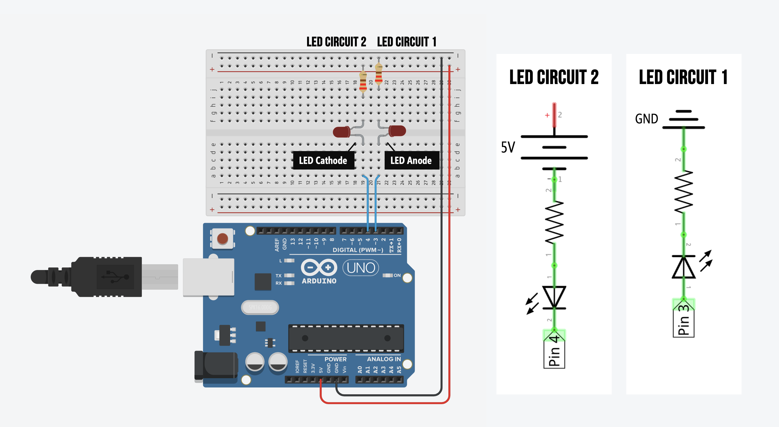
Step 3: Wire up the second LED circuit
Now wire up the second LED circuit. This time, however, connect the LED cathode (short leg) to Pin 4 and the resistor to the 5V rail.
Writing the code: blinking Pins 3 and 4
Let’s write code to blink the LEDs hooked up to Pins 3 and 4.
Importantly, the Pin 3 circuit (LED Circuit 1) will turn on with digitalWrite(3, HIGH) whereas the Pin 4 circuit (LED Circuit 2) will turn off with digitalWrite(4, HIGH). Why? Recall that current always flows from high voltage potential to low voltage potential.
When Pin 3 is HIGH (5V), there is a voltage difference between Pin 3 and GND so current flows from Pin 3 to ground. When Pin 4 is HIGH (5V), however, there is no voltage difference across the circuit (from Pin 4 to 5V) and thus, no current. This behavior is illustrated in the animation below.
Let’s write the code!
Step 1: Write the setup and initialization code
const int LED1_OUTPUT_PIN = 3; // Anode faces Pin 3 (cathode connected to 0V)
const int LED2_OUTPUT_PIN = 4; // Cathode faces Pin 4 (anode connected to 5V)
const int DELAY_MS = 1000; // delay for 1 sec between blinks

// The setup function runs once when you press reset or power the board
void setup() {
  // Set our LED pins as output
  pinMode(LED1_OUTPUT_PIN, OUTPUT);
  pinMode(LED2_OUTPUT_PIN, OUTPUT);
}
Step 2: Write the blink code in loop()
// The loop function runs over and over again forever
void loop() {
  // Below, you're going to see that driving Pin 3 HIGH will turn on LED1
  // but driving Pin 4 HIGH will actually turn *off* LED2
  digitalWrite(LED1_OUTPUT_PIN, HIGH);  // turns ON LED1
  digitalWrite(LED2_OUTPUT_PIN, HIGH);  // turns OFF LED2
  delay(DELAY_MS);                      // delay is in milliseconds; so wait one second

  digitalWrite(LED1_OUTPUT_PIN, LOW);   // turns OFF LED1 (Pin 3 is now 0V and other leg of LED is 0V)
  digitalWrite(LED2_OUTPUT_PIN, LOW);   // turns ON LED2 (Pin 4 is now 0V and other leg of LED is 5V)
  delay(DELAY_MS);                      // wait for a second
}
Step 3: Compile, upload, and run the code!
We did it! Now compile and upload the code.
And here’s a top-down video with the code window:
Our Blink2 code on GitHub
You can access our Blink2 code in our Arduino GitHub repository. It’s also displayed below:
This source code is on GitHub.
Exercises
Want to go further? Here are some things to try:
- Same configuration. What happens if you wire both LEDs in the current-source configuration (anode toward the pin, cathode toward GND)? How does the blinking behavior change compared to having one source and one sink?
- Different blink rates. Try using different delay values for turning each LED on and off. Can you make LED Circuit 1 blink faster than LED Circuit 2 using this code structure? What limitations do you run into? (Hint: we’ll solve this properly in L8: Rate Blinking LEDs.)
- Add Serial debugging. Add
Serial.printstatements to output which LEDs are on and off at each step. Use the Serial Plotter to graph the pin states—you should see two inverted square waves.
Lesson Summary
In this lesson, you explored two fundamental output configurations. You learned:
- How Arduino GPIO pins can act as current sources (driving current out of the pin to
GND). - How Arduino GPIO pins can act as current sinks (allowing current to flow into the pin from a higher voltage source like 5V).
- That driving a sink pin
HIGH(5V) actually turns the connected LED off because there is no voltage difference across the circuit.
Next Lesson
In the next lesson, we will use a new component—an RGB LED—to output a variety of colors beyond just red, and we will apply our new knowledge of sourcing and sinking to understand Common Anode vs. Common Cathode RGB LED designs!