Lesson 8: Variable Resistors
Table of Contents
- Variable resistor types
- Potentiometers
- Activity: Build LED circuit with potentiometer as variable resistor
- Activity: Swap in another variable resistor
- Activity: build your own DIY variable resistor
- Resources
- What’s next?
In previous lessons, we worked with fixed-value resistors. In this lesson, we’ll learn about variable resistors—resistors that change their resistance in response to some physical input (like potentiometers) or environmental input like thermistors (temperature), force-sensitive resistors (force), or photo-sensitive resistors (light). We’ve listed some examples below.
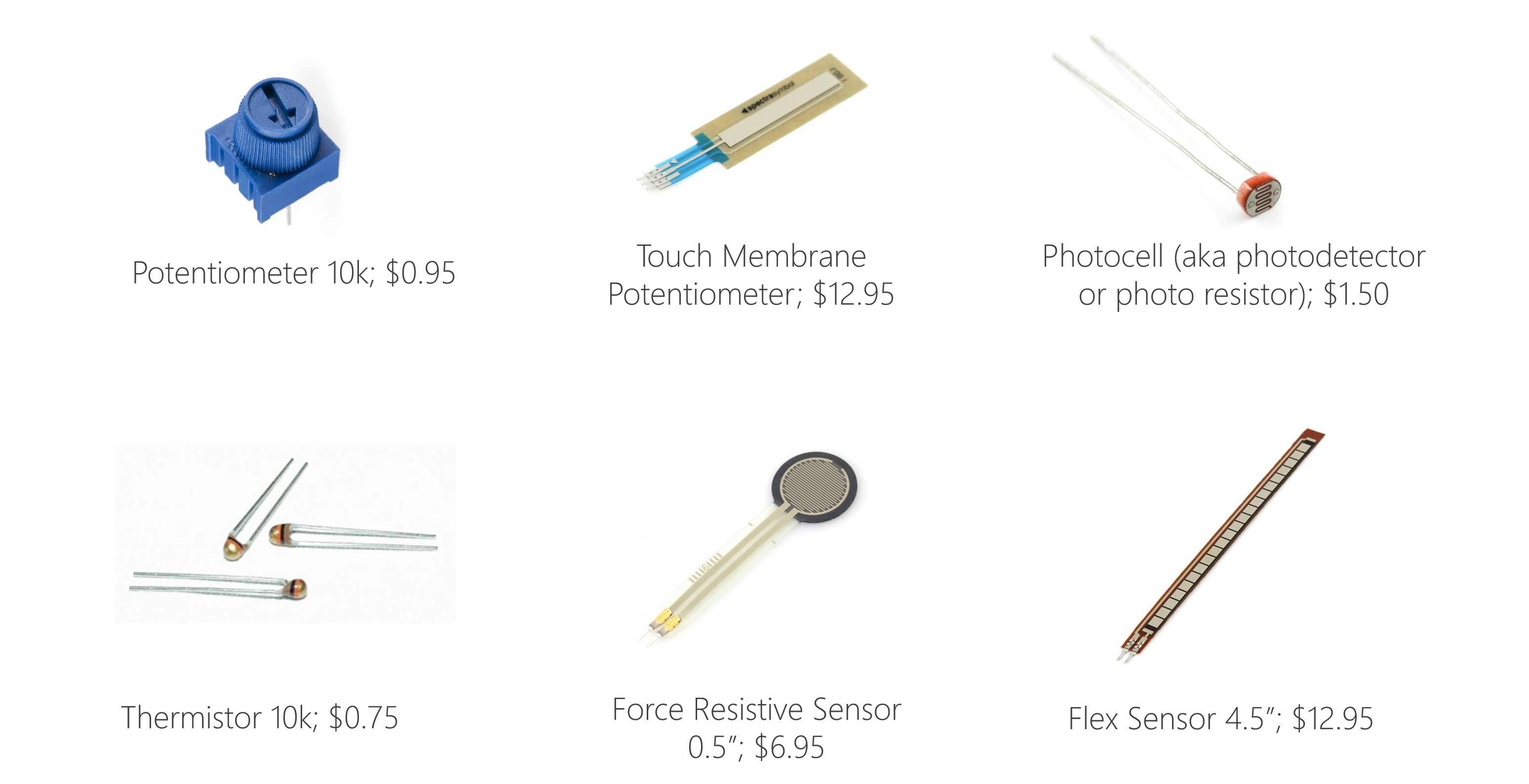 Figure. Many common sensors are actually variable resistors—they dynamically change their resistance in response to some human or environmental input. For example, thermistors change their resistance based on temperature, photocells based on light, force-sensitive resistors (FSRs) based on force. In fact, you have thermistors, photocells, and FSRs in your hardware kits! Prices and pictures are from Sparkfun.com; parts can often be cheaper in bulk from suppliers like Digi-Key or Mouser Electronics.
This is exciting! Physical computing is all about interaction and resistive materials that respond to different stimuli open up a new world of possibilities!
Variable resistor types
There are two-leg (or “two-terminal” or “two-lead”) variable resistors like rheostats, photocells, and force-sensitive resistors and there are three-leg variable resistors, which are called potentiometers. Both types are orientation agnostic—just like regular resistors, they will work in either direction (non-polarized). See schematic symbols below.
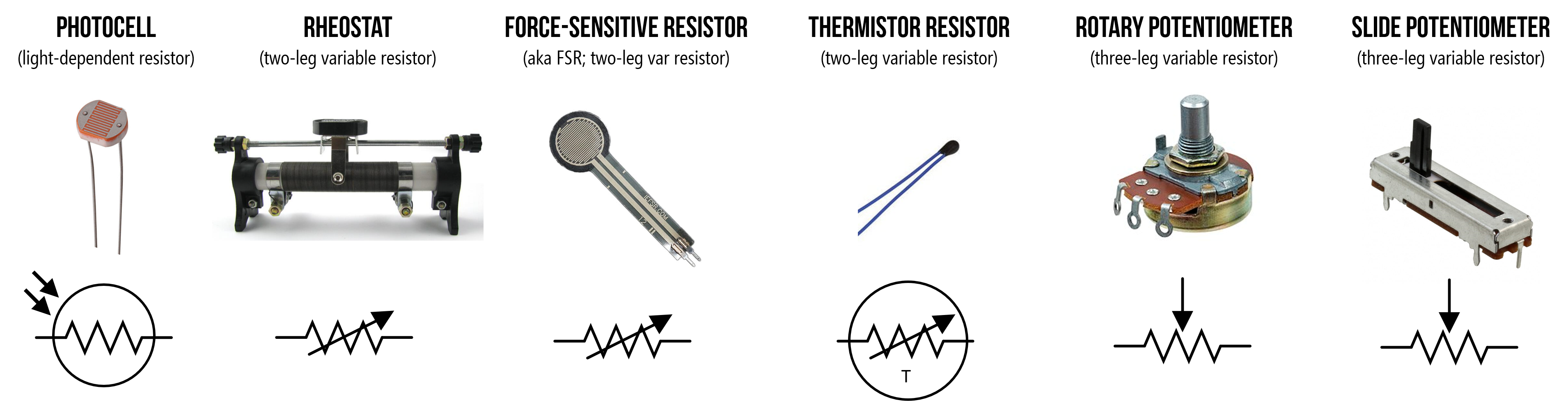 Figure. Schematic symbols for some example two-leg and three-leg variable resistors. Notice how some schematic symbols are the same across variable resistor types.
Regardless of specific type, all variable resistors have a schematic symbol similar to a regular resistor but with some visual modification to indicate “variability.” A few general things to note:
- The two-leg variable resistor schematic symbol looks quite similar to a regular resistor but has a diagonal line through it indicating variability
- Potentiometers have three legs, which are also represented in the schematic. The middle arrow (the “wiper leg”) can be connected in a circuit and will actually be shown that way in a circuit diagram. We’ll see this below.
- Some common variable resistors, like light-dependent resistors (LDRs or photocells), have their own schematic symbols. Others, like force-sensitive resistors and rheostats share the same symbol.
Potentiometers are probably the most common type of variable resistor and an important component to learn about, so let’s get started!
Potentiometers
A potentiometer (or pot) is a three-terminal resistor with a sliding or rotating contact that can be used to dynamically vary resistance.
Video. This animation shows how the wiper can be used to vary resistance in a rotary potentiometer. The figure on the right is the formal electrical symbol. Animation by Jon Froehlich. Created in PowerPoint.
Potentiometers are truly ubiquitous electronic components found in everything from volume controls to analog joysticks. In our UW courses, we often provide 10kΩ potentiometers in our kits like the 10K panel mount potentiometer and 10K trim potentiometer, shown below.
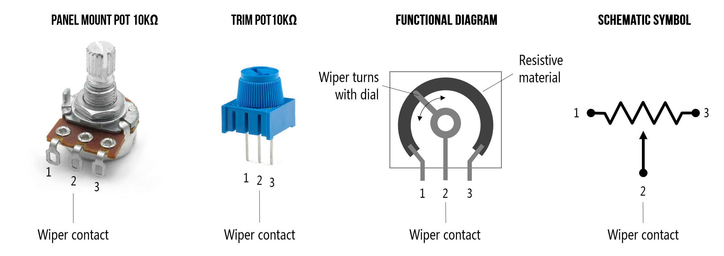 Figure. Two example potentiometers commonly included in our hardware kits: a 10kΩ panel mount and a 10kΩ trim potentiometer.
While potentiometers are often used as human input devices, this is not always the case. For example, a potentiometer might be used in a feedback circuit for a servo motor. As the motor rotates, it also rotates an embedded potentiometer’s control dial (wiper), which feeds back rotational information to the control circuit (see Chapter 15.4 on RC Servos in Scherz and Monk, 2016).
Though still widely used, some of a potentiometer’s application spaces have been subsumed by digital controls like rotary encoders and buttons. Don’t get confused: rotary encoders can look very similar to potentiometers—indeed, with knobs attached they can look identical. However, rotary encoders are not resistive devices, require digital circuits to use, and can be spun around continuously. In contrast, potentiometers are resistive components, can be used in analog or digital circuits, and typically have a controllable angle of 200°-270°.
How does a potentiometer work?
Potentiometers have three legs: the resistance between the outer two legs (Leg 1 and Leg 3) will not vary. For example, if you are using a 10kΩ potentiometer, then the resistance between Legs 1 and 3 will always be 10kΩ regardless of wiper position (Leg 2). If you’re using a 1kΩ potentiometer, then the resistance between Legs 1 and 3 will be 1kΩ, and so on.
The power of a potentiometer is in that middle leg (Leg 2) whose resistance varies depending on the potentiometer’s sliding or rotating contact (the wiper) position. It may help to think of a potentiometer as containing two interdependent resistors \(R_1\) and \(R_2\) that always sum to \(R_{Total}\) (where \(R_{Total}\) is the potentiometer’s total value like 1kΩ or 10kΩ). As you move the slider contact, \(R_1\)’s resistance will increase as \(R_2\)’s resistance decreases. See animation below.
Video. Animation by Jon Froehlich. Created in PowerPoint.
Using two multimeters set to measure resistances across both Legs 1-2 and 2-3, we can examine this behavior directly. Notice how as you move the wiper, the resistance across Legs 1 and 2 (\(R_{1}\)) and Legs 2 and 3 (\(R_{2}\)) proportionally change but always sum to \(R_{total}\). We are using a 10kΩ potentiometer so \(R_{total}=10kΩ\)
Video. Using two multimeters, we can examine how the resistances change between Legs 1-2 and 2-3. Note that the resistance between the outer legs (Legs 1-3) will always sum to potentiometer’s total value. In this case, we’re using a 10kΩ, so it would sum to 10kΩ. Try it out on Tinkercad here.
Potentiometer types
Potentiometers come in a range of sizes, power ratings, and physical designs. Some larger designs can handle several watts of power (capable of dissipating a lot of heat) while smaller, surface-mounted designs are rated for only a fraction of a watt (just like the \(\frac{1}{4}\) watt resistors in your kits).
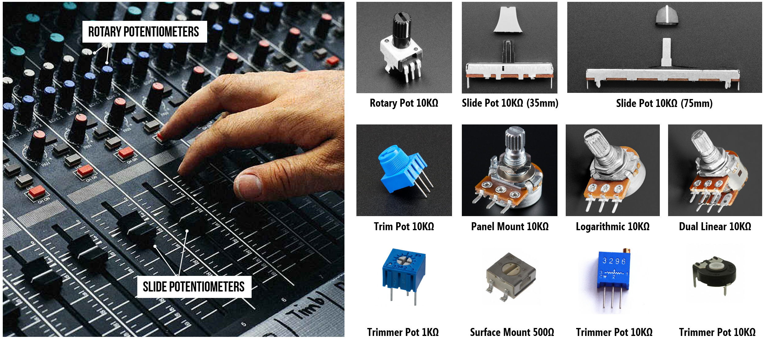 Figure. Potentiometers are ubiquitous input devices found in everything from cars to audio mixing boards. There are nearly infinite designs, so we’re only showing a small sample above. Note that you cannot tell the resistance value of a potentiometer (or pot) simply by looking at it nor can you tell whether it is a linear taper or a logarithmic taper. Logarithmic potentiometers are common in audio applications (because the human ear senses loudness logarithmically). Images sources: the potentiometer pictures with dark backgrounds are from Adafruit. The others are from digikey.
Potentiometers differ primarily in terms of:
-
Resistance range. Just like resistors, potentiometers are designed to provide different resistances but over a range (0-1kΩ and 0-10kΩ are common).
-
Linear vs. logarithmic tapers (or tracks). With linear potentiometers, the resistance varies linearly as the wiper is moved. With logarithmic potentiometers, the resistance varies logarithmically. The latter type is common in audio applications because the human ear perceives sound magnitude logarithmically with more sensitivity for quiet sounds and less for loud sounds.
-
Power dissipation. Again, similar to resistors, potentiometers have different “power ratings”, which correspond to their ability to dissipate heat. This trim potentiometer datasheet states that the power rating is 0.5W while this panel mount potentiometer is rated at 0.1-0.2W (see datasheet).
-
Rotary vs. slider. Rotary potentiometers use a rotating knob to control the wiper leg while slider potentiometers use a slider.
-
Mount. Some potentiometers are built for “mounting”, for example, in a car dashboard or audio mix board. Others are built for breadboarding or for mounting on printed-circuit boards (so-called “surface-mount” potentiometers).
-
Knob. For those potentiometers used for human-input applications, there are a variety of knob types to support ergonomic and grippable interaction.
Inside a potentiometer
If you’re curious about how a potentiometer is constructed, this video by John Cooper provides a wonderful deconstruction of rotary potentiometers and how they work.
Video. A video deconstruction of potentiometers and how they work by John Cooper (on YouTube).
Potentiometer knobs
You have very likely interacted with potentiometers many times in your life; however, they have been covered by knobs, which make the potentiometer more ergonomic and grippable.
There are a large diversity of knobs, which fit both panel-mount potentiometers and rotary encoders, used in a variety of user-facing applications like audio mixers, joysticks, and control panels. Take a look at some examples below:
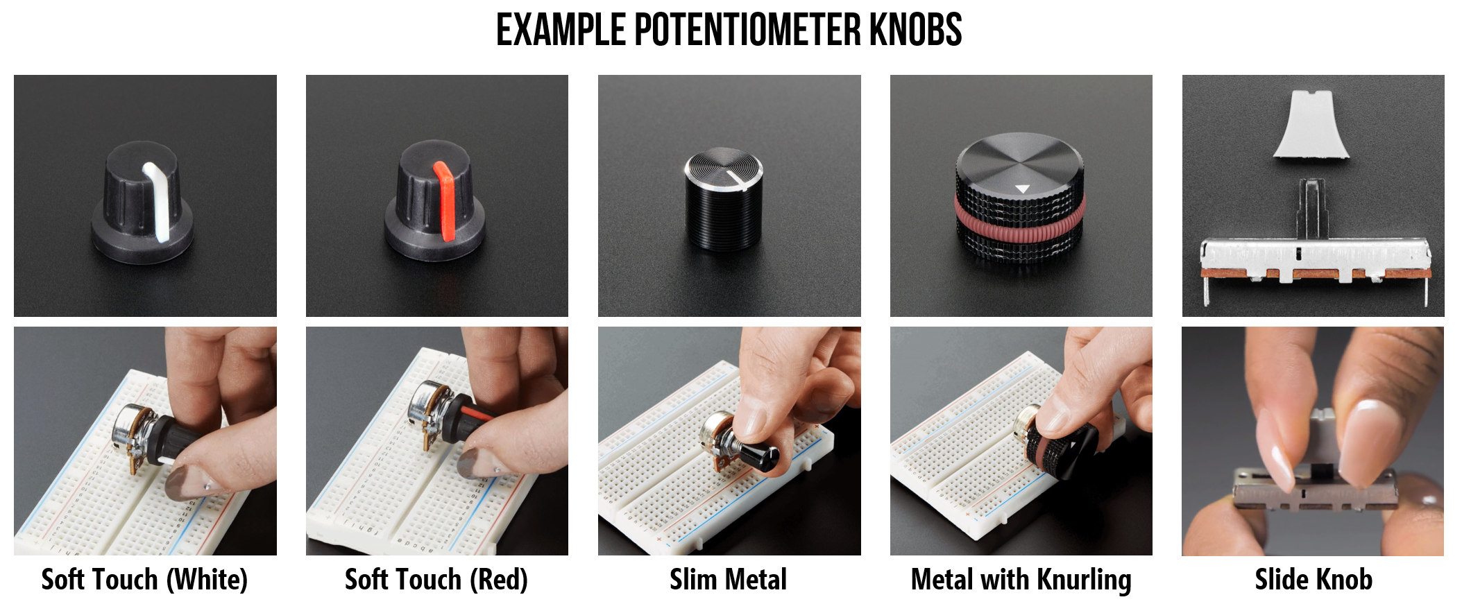 Figure. Small sample of potentiometer and rotary encoder knobs. All images from Adafruit. From left-to-right: Soft Touch T18 - White, Soft Touch T18 - Red, Slim Metal Knob, Machined Metal Knob, Slide Pot with Plastic Knob
Creating custom 3D-printable knobs
A fun introductory 3D-printing exercise is to design, model, and print your own potentiometer knob. We typically do this activity at the beginning of our fabrication module in our physical computing course. Here are some simple example 3D-printable potentiometer knobs that we designed.
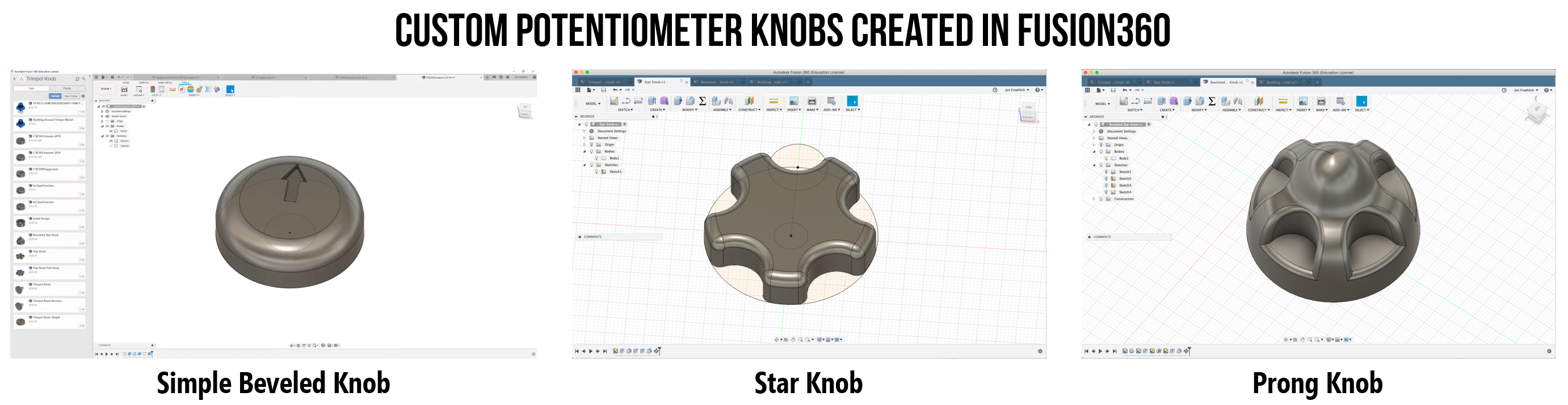 Figure. Three simple potentiometer knobs created in Fusion 360 (in 5-10 minutes each). The CAD designs take roughly 20 minutes to print on an Ultimaker 2+ 3D printer with 0.2mm layer height and no supports or plate adhesion (e.g., brims). All designs by Jon Froehlich. You can see step-by-step tutorial videos here and here.
Even more fun is to combine your custom 3D prints with a microcontroller and to build custom applications that create new interactive experiences.
Video. A short video demonstrating the custom 3D printed potentiometer knobs being used as custom game controllers with an Arduino Leonardo and custom Processing sketches. The code for the Arduino+Processing “Etch-a-sketch” is here and the code for the Arduino+Processing “Pong” is here. All 3D CAD designs and code by Jon Froehlich.
Potentiometers as analog joysticks
Just as our 3D-printed designs hint at, potentiometers have a long history as game controllers. In our hardware kits, we often include a 2-axis joystick like this one from Parallax ($6.95 on Adafruit), which contains two embedded 10kΩ potentiometers.
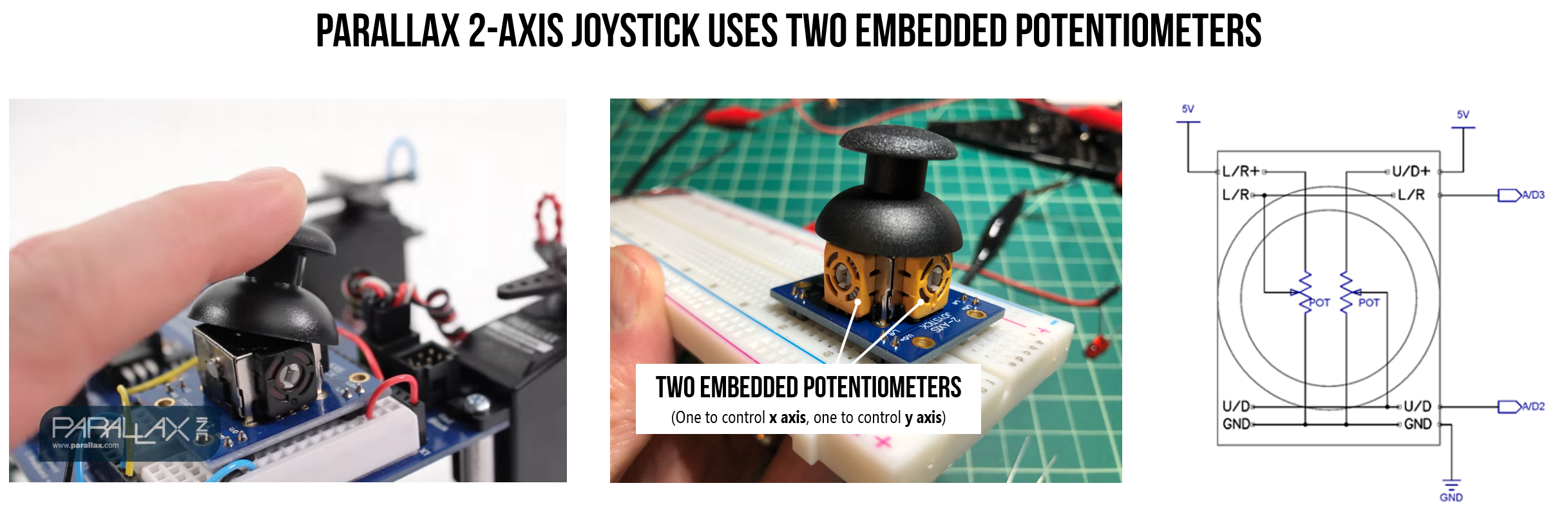 Figure. The Parallax 2-Axis Joystick has two embedded 10 kΩ potentiometers, one for each axis. You can see a video demo here.
By moving the analog joystick, you independently control the two potentiometers in a voltage divider configuration. There is a \(V_{Out}\) for the “Up/Down” potentiometer and a \(V_{Out}\) for the “Left/Right” potentiometer. See the circuit diagram above.
Video. A short snippet from this official Parallax video showing how physical movement of the joystick is translated into an electrical signal using two potentiometers.
Potentiometers as voltage dividers
Potentiometers are actually conveniently packaged voltage dividers, which we first described in Lesson 4: \(R_{1}\) and \(R_{2}\) divide the voltage as the potentiometer wiper moves.
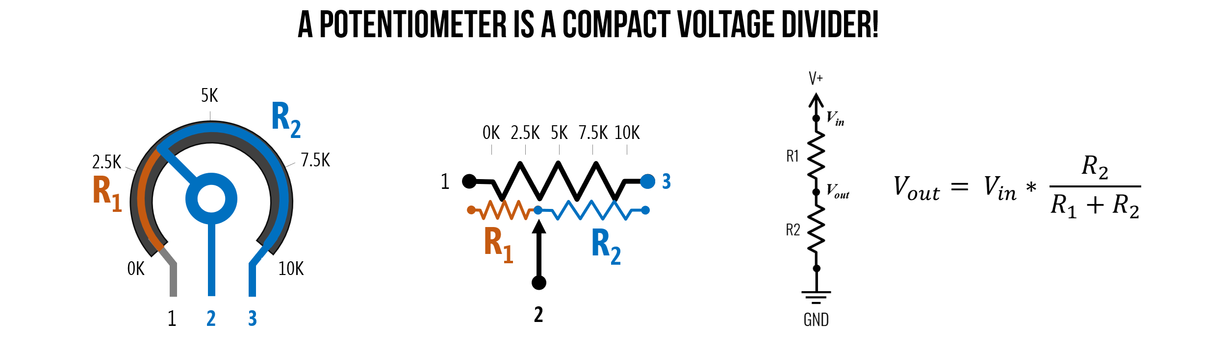 Figure. A potentiometer is a compact voltage divider. Image made in PowerPoint.
As an example, let’s hook up a potentiometer to 5V (Leg 1) and ground (Leg 3) and see the output voltage \(V_{out}\) vary at the wiper leg (the signal at Leg 2):
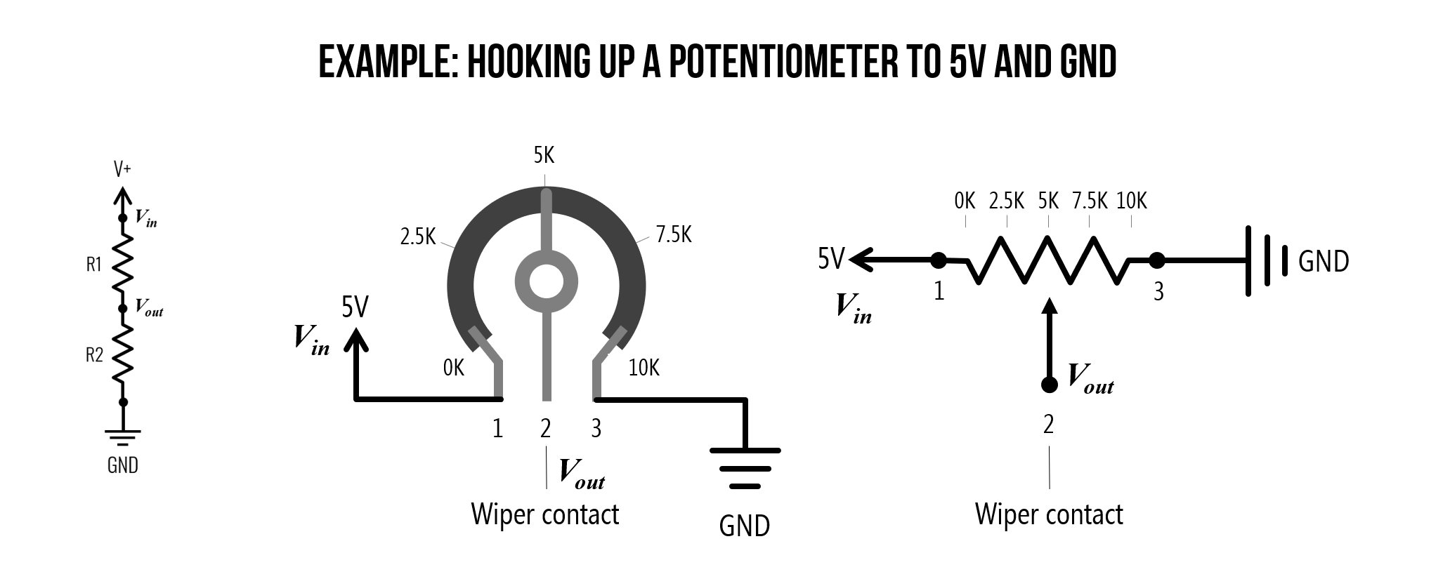 Figure. Let’s hookup the potentiometer to a 5V and ground. Image made in PowerPoint.
Now, let’s see what happens as we change the wiper. Notice how \(V_{out}\) changes according to \(V_{in} * \frac{R2}{(R1 + R2)}\). In the video below, we are using a 1kΩ potentiometer but the function is the same.
Video. A demonstration of how \(V_{out}\) changes according to \(V_{in} * \frac{R2}{(R1 + R2)}\). Animation made in PowerPoint and CircuitJS.
Using a potentiometer as a two-terminal variable resistor
When only two terminals (or legs) of the potentiometer are used—an outer leg and the wiper (or signal) leg—the potentiometer acts as a rheostat or a two-terminal variable resistor. You might use a potentiometer in this configuration to vary the resistance in your circuit rather than as a voltage divider. In fact, this is what we’ll do below. We’ll return to using a potentiometer as a voltage divider when we start working with microcontrollers.
Activity: Build LED circuit with potentiometer as variable resistor
Whew, now we’re ready to build stuff! Let’s start by building a simple LED circuit with our potentiometer as a two-terminal variable resistor. Here, we will only use one outer leg (either Leg 1 or 3, it doesn’t matter) and the signal leg (Leg 2). Let’s take a look at the circuit diagram—is it what you expected? Why or why not?
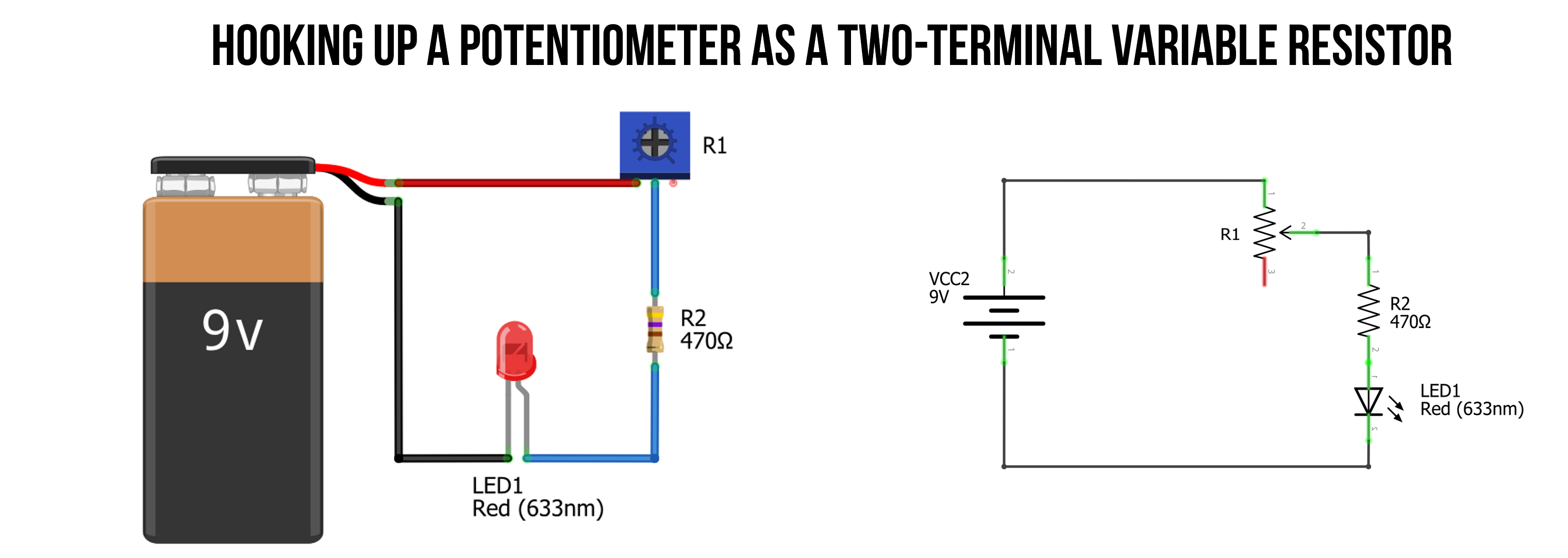 Figure. An example of how to hook up a potentiometer as a variable resistor. Image made in Fritzing and PowerPoint.
Do you notice that additional fixed-value resistor in our circuit? Why do you think we have it?
Because many potentiometers go from 0Ω to their max value, we must use a “backup” resistor in series with our potentiometer. Otherwise, when we rotate the potentiometer to low resistance values, too much current will go through our LED. For example, with a typical red LED with \(V_f=2V\) and a 9V battery, if we set the potentiometer to 50Ω, then we will have \(I=\frac{7V}{50Ω}=140mA\), which is far beyond the 20–30mA threshold of the LED.
Always use a backup resistor with variable resistors and LEDs. This applies not just to potentiometers but to all variable resistors, including FSRs and photocells. A 220Ω or 330Ω backup resistor in series ensures the current never exceeds safe levels regardless of the variable resistor’s position.
Video. Here’s an example of what would happen if you rotated the potentiometer to low resistance without a backup resistor. Boom, another blown out LED. Video made with Tinkercad and Camtasia.
You can, of course, also build a potentiometer-based circuit in CircuitJS like this one.
Prototype circuit in Tinkercad Circuits
We’d like you to prototype two potentiometer-based LED circuits in Tinkercad Circuits: the first without a breadboard and the second with a breadboard. If you’d like, you can include an ammeter and voltmeter showing how the current and voltage drops change as you rotate the potentiometer knob. Here are two possible examples of potentiometer-based LED circuit. Make sure both the pictorial representations and circuit schematics make sense. Remember, we are only using two of the three legs of the potentiometer.
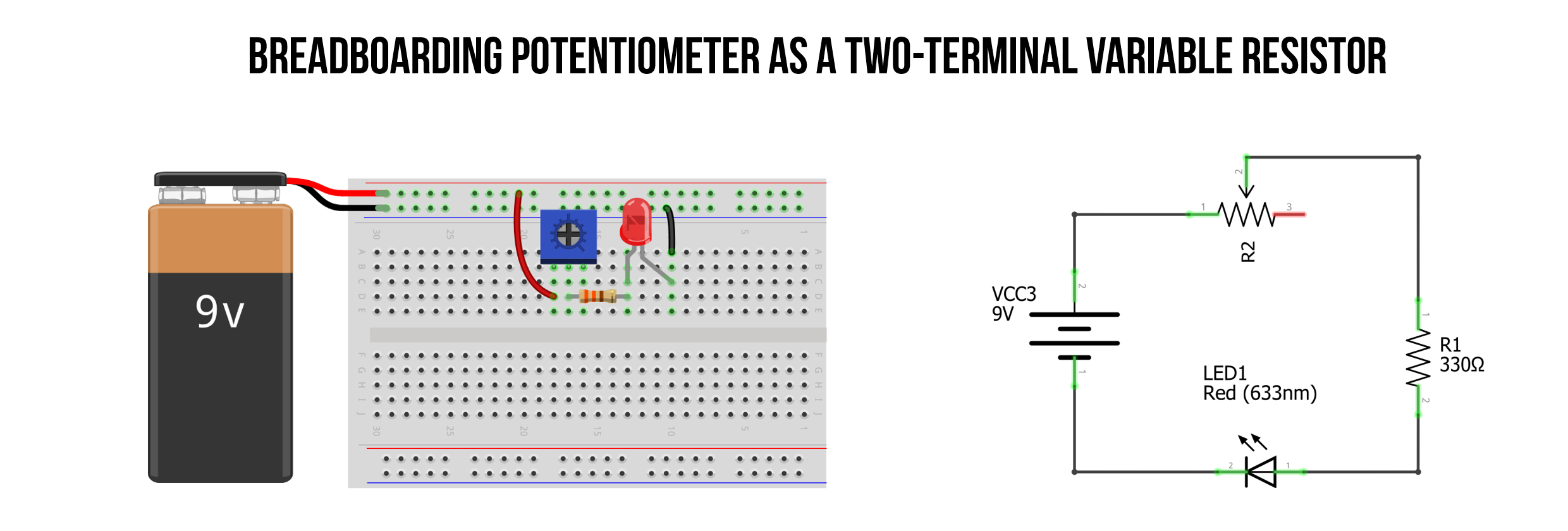 Figure. An example of how to hook up a potentiometer as a variable resistor with a breadboard. Many other possible functionally equivalent circuits exist. Image made in Fritzing and PowerPoint.
For both Tinkercad Circuits, include a screenshot in your prototyping journals and describe your observations (just a sentence or two is fine).
Prototype circuit on breadboard
After you’ve built and simulated the circuits in Tinkercad, we’d like you to physically build the breadboarded version with your hardware kits. Take a photo and a quick demo video of the circuit working and put them in your prototyping journals. Describe any challenges.
Video. Here’s one possible way to breadboard a trim potentiometer circuit with a backup resistor and red LED. What did you make? Please take a similar video for your prototyping journals.
Activity: Swap in another variable resistor
After you finish the above, we would like you to play and experiment with other variable resistors in your hardware kits, which include the thermistor (in your Plusivo box), the light-dependent resistor (also in your Plusivo box), the slide potentiometer, and/or my favorite, the force-sensitive resistor.
Choose two of these and swap them in instead of the trim potentiometer on your breadboard. Take some photos, a video demo, and write a brief description of what you observed/learned for your prototyping journals.
We provide two examples below.
Force-sensitive resistor circuit
The force-sensitive resistor (FSR) responds to force or pressure. As an applied force increases, the resistance across the two terminals decreases. In the simple circuit below, the LED will receive more current (and emit more light as a result) as more pressure is applied to the FSR.
 Figure. An example of how to hook-up a force-sensitive resistor for a simple LED circuit. Image made in Fritzing and PowerPoint.
Here’s a video demonstration:
Video. A video demonstration of an FSR-based LED circuit.
Light-dependent resistor circuit
A light-dependent resistor (LDR)—sometimes called a photocell or photo-sensitive resistor—reduces its resistance in response to light. In the simple circuit below, you’ll notice that the red LED illuminates brightly in response to a flashlight. In many practical applications, you’d actually want the opposite behavior—for example, an automatic nightlight that brightens an LED when it gets dark. Achieving inverted behavior with just passive components requires more complex circuitry, but it becomes straightforward once we start using microcontrollers, which can read the LDR voltage and programmatically control the LED.
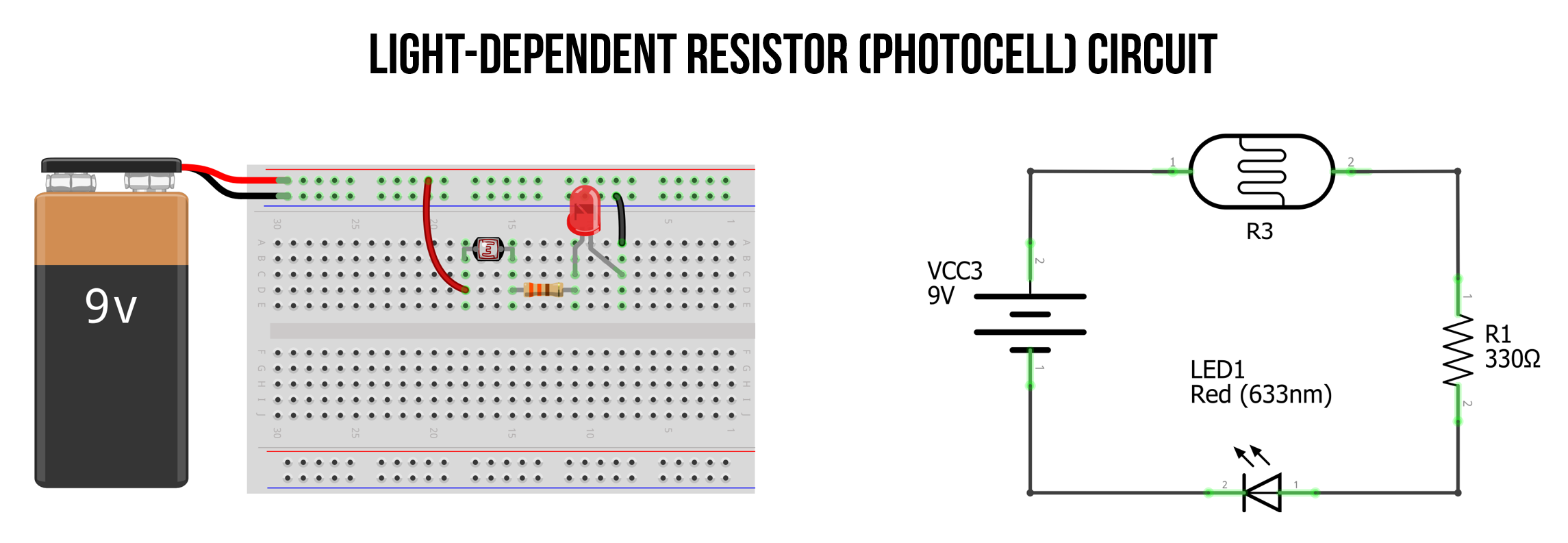 Figure. An example light-dependent resistor (LDR) circuit with an LED. In this configuration, the LED brightness will increase in proportion to the amount of light cast on the LDR sensor. Image made in Fritzing and PowerPoint.
And the video demonstration:
Video. A video demonstration of an LDR-based LED circuit.
Activity: build your own DIY variable resistor
For the final activity, we’d like you to build your own DIY variable resistor. We included 12B graphite pencils in your hardware kits for just this purpose but you can use other materials if you so choose.
Pencil leads are mixtures of clay and graphite—the more graphite, the more conductive. The more graphite, the higher the B rating (you can get 1B, 2B, 3B… 14B pencils). For your kits, we got 12B.
This activity is inspired by Jeff Feddersen, from NYU’s ITP program. Please watch this video before continuing (it’s one of my favorites!).
Ohm Part 2 from Jeff Feddersen on Vimeo.
For your prototyping journals, sketch out the circuit diagram for the DIY potentiometer, physically build it, and then take some photos and a video demonstrating how it works. Please also include a brief description and a reflection of what you learned.
Example DIY rotary potentiometer
Here is an example DIY rotary potentiometer I made out of some cardboard, paper, a paper clip and a thumb tack (for the wiper), and a 12B pencil sketch (for the resistive material).
Video. A lo-fi rotary potentiometer made out of some cardboard, paper, a paper clip and a thumb tack (for the wiper), and a 12B pencil sketch (for the resistive material).
Example DIY slider potentiometer
Here is an example DIY slider potentiometer I made out of similar materials: cardboard, paper, a cardboard wiper with copper tape, and some 12B pencil sketch (for the resistive track).
Video. A lo-fi slider potentiometer made out of some cardboard, paper, copper tape-wrapped cardboard (for the slider), and a 12B pencil sketch (for the resistive track).
Other variable resistors worth knowing about
Beyond the sensors in your kits, there are many other variable resistors used in physical computing. Flex sensors (or bend sensors) change resistance as they are bent—they’re commonly used in wearable computing, robotic gloves, and game controllers (the original Nintendo Power Glove used flex sensors!). Stretch sensors use conductive materials that change resistance as they are stretched, useful for wearable applications that track body movement.
DIY lo-fi electronics
There are lots of great resources for building lo-fi sensors, buttons, and connectors using everyday craft materials like tinfoil, cardboard, and paper clips. See these resources to help kickstart your brainstorming!
-
The KOBAKANT DIY Wearable Technology website by Mika Satomi and Hannah Perner-Wilson has a wonderful set of resources for crafting your own electronic components, including sensors, actuators, traces, and connectors.
-
Similarly, the “kit-of-no-parts” website describes multiple methods for handcrafting electronics and sensors.
-
Scrappy Circuits by Michael Carroll covers cardboard-based circuits. See their social media for more ideas.
Resources
-
Chapter 8, Variable Resistors, Hughes, Practical Electronics: Components and Techniques, O’Reilly Media, 2015.
-
Chapter 11: Potentiometer in Platt, Make: Encyclopedia of Electronic Components Volume 1: Resistors, Capacitors, Inductors, Switches, Encoders, Relays, Transistors, O’Reilly, 2012.
What’s next?
Congratulations — you’ve completed the Intro to Electronics tutorial series! You now understand the fundamentals of voltage, current, and resistance; how to analyze circuits using Ohm’s Law; how to work with resistors, LEDs, and variable resistors; and how to prototype circuits on breadboards.
You’re now ready to start our Intro to Arduino series, where you’ll combine everything you’ve learned with a programmable microcontroller to build truly interactive devices!