Lesson 3: Servo Motors
Table of Contents
- Materials
- Servo motors
- Servo PWM vs.
analogWrite()PWM - The Arduino Servo library
- Wiring
- Let’s make stuff!
- Troubleshooting
- Exercises
- Lesson Summary
- Resources
- Next Lesson
This lesson is in draft form. The circuit diagrams and videos have not yet been inserted; however, the content is complete and can be followed.
In the previous two lessons, we controlled pixels—on an OLED screen and on an LED strip. Now let’s make things move! Servo motors let you precisely control angular position, making them essential components in robotics, robotic arms, RC vehicles, pan/tilt camera mounts, automated door locks, and countless other projects. Best of all, like the OLED and addressable LEDs, servos have a built-in control circuit—so the wiring is simple and a library handles the tricky signal timing.
In this lesson, you will learn:
- What servo motors are and how they differ from regular DC motors
- How the internal feedback loop (motor + gears + potentiometer + control circuit) enables precise position control
- The difference between servo PWM signals and
analogWrite()PWM—and why they’re not the same thing- How to use the Arduino Servo library to control servo position
- How to wire a servo to Arduino (no transistor needed!)
- Power considerations for servos and when to use an external supply
- How to create interactive servo projects driven by sensor input
Materials
You will need the following materials for this lesson:
| Arduino | Servo Motor | Breadboard | Potentiometer |
|---|---|---|---|
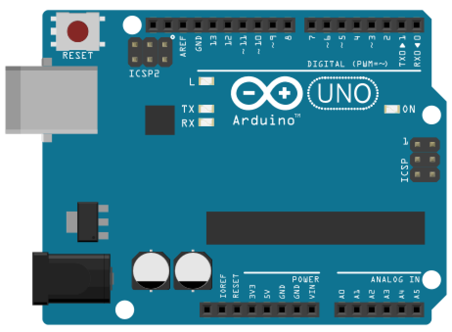 |  | 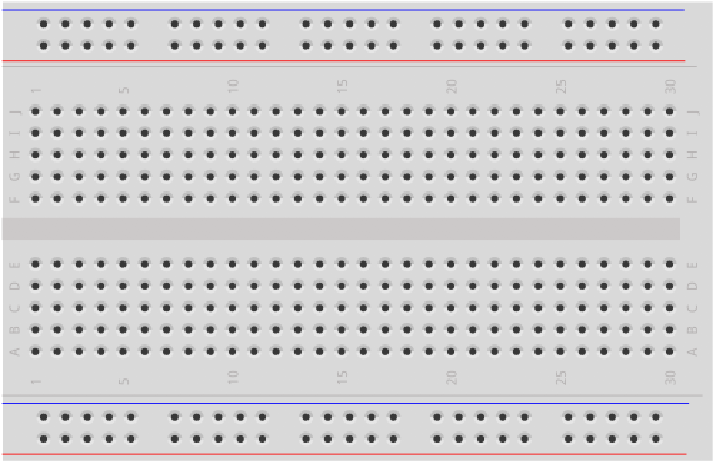 | 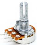 |
| Arduino Uno, Leonardo, or similar | SG90 or SG92R micro servo (9g) | Breadboard | 10KΩ Potentiometer |
You will also need jumper wires and, for Activity 3, a couple of tactile buttons.
Our kits include a 9g micro servo—either the TowerPro SG92R (available from Adafruit) or the Miuzei SG90 (available from Amazon). Both are SG90-class servos with nearly identical specs and wiring. Any 9g micro servo with a standard 3-pin connector will work for this lesson.
Servo motors
What is a servo motor?
A servo motor is a motor that can rotate to a specific angle and hold that position. Unlike a regular DC motor (which just spins continuously when you apply voltage), a servo knows where its output shaft is pointing and actively works to maintain that position—even if you try to push it away.
How does it do this? A servo packs four components into one compact package:
- A small DC motor that provides rotational force.
- A gear reduction system that slows the motor down while increasing torque (turning force).
- A potentiometer mechanically coupled to the output shaft that measures the shaft’s current angle.
- A control circuit that continuously compares the desired position (from your Arduino’s signal) with the actual position (from the potentiometer) and drives the motor until they match.
This is called a closed-loop feedback system—the control circuit constantly monitors and corrects the position. You tell the servo “go to 90°” and it figures out how to get there and stay there.
Built-in smarts! Notice the pattern across this module: the OLED has a built-in SSD1306 display controller, addressable LEDs have built-in WS2812B driver chips, and servos have a built-in feedback control circuit. Each device handles the complex low-level work internally, and you communicate with it through a simple signal. In the next lesson, we’ll encounter a component that doesn’t have built-in intelligence—and you’ll appreciate the difference!
Standard vs. continuous rotation servos
There are two types of hobby servos:
- Standard (positional) servos rotate to a specific angle, typically between 0° and 180°, and hold that position. The angle is determined by the signal you send. This is what we’ll use in this lesson.
- Continuous rotation servos spin freely like a regular motor, but you control their speed and direction rather than their position. The same PWM signal that means “go to 90°” on a standard servo means “stop” on a continuous rotation servo, while signals at one extreme produce full speed in one direction and signals at the other extreme produce full speed in the opposite direction.
For this lesson, we’ll focus on standard (positional) servos, specifically the popular SG90 micro servo.
The SG90 micro servo
The SG90 is a class of tiny, inexpensive servo motors that weigh only 9 grams. Despite their small size, they’re surprisingly capable! You’ll find SG90-class servos from many manufacturers (TowerPro, Miuzei, and others)—they all share the same basic form factor, connector, and specs:
| Attribute | Rating |
|---|---|
| Weight | 9g |
| Operating voltage | 4.8V - 6.0V |
| Stall torque | 1.8 kg·cm (4.8V) |
| Operating speed | 0.09 sec/60° (4.8V) |
| Rotation range | ~180° |
| Idle current | ~6mA |
| Running current (no load) | ~200-500mA |
| Stall current | ~500-700mA |
The SG90 has a standard 3-pin connector with color-coded wires: orange/yellow (signal), red (power), and brown/black (ground).
“SG90” is a form factor, not a single manufacturer’s product. The specs above are approximate and vary between manufacturers. You may see slightly different torque, speed, or current ratings on different datasheets—this is normal.
Servo PWM vs. analogWrite() PWM
Before we start wiring, let’s clear up a common source of confusion. You’ve already used analogWrite() to control LED brightness. Servos are also controlled by a “PWM” signal. Both signals technically have a duty cycle (the fraction of each period that the signal is HIGH), but the receiver interprets them in completely different ways—and mixing them up is a common mistake.
analogWrite() PWM | Servo PWM | |
|---|---|---|
| Purpose | Power modulation (average voltage) | Position encoding (communication signal) |
| How the receiver interprets it | Averages the on/off switching into a voltage level (50% duty cycle ≈ 2.5V) | Measures the HIGH pulse duration to decode a target angle |
| Frequency | 490 Hz or 980 Hz (fast enough to smooth power delivery) | 50 Hz (one pulse every 20ms) |
| What you control | Duty cycle: 0–255 → 0–100% average power | Pulse width: ~1ms → 0°, ~1.5ms → 90°, ~2ms → 180° |
| Arduino API | analogWrite(pin, 0-255) | servo.write(0-180) via the Servo library |
An LED connected to analogWrite() at 50% duty cycle sees ~2.5V average and glows at half brightness—it doesn’t care when the pulses arrive, only how much total energy it receives. A servo’s control circuit does the opposite: it ignores the average power level and instead precisely measures the width of each HIGH pulse to determine the target angle. A 1.5ms pulse means ‘go to 90°’ regardless of frequency—in principle. In practice, hobby servos are designed for 50 Hz, but the point is that the position information lives in the pulse width, not the duty cycle ratio.
Video. A video snippet from Engineering Mindset showing the PWM waveform driving a servo motor. Notice how the pulse width—the duration of the HIGH pulse within each period—controls the servo’s target angle.
Do not use
analogWrite()to control servos! TheanalogWrite()function produces PWM at 490 Hz or 980 Hz—much too fast for servos, which expect 50 Hz. Sending the wrong signal can cause erratic behavior or damage. Always use the ArduinoServolibrary, which generates the correct 50 Hz signal for you.
The Arduino Servo library
The Arduino Servo library ships with the Arduino IDE—no installation needed. It handles all the precise 50 Hz signal timing so you can simply tell the servo which angle you want.
Key API
#include <Servo.h>

Servo myServo;              // Create a Servo object

void setup() {
  myServo.attach(3);        // Attach to pin 3 (any digital pin works)
  myServo.write(90);        // Move to 90° (center position)
}
Here are the most commonly used functions:
| Function | Description |
|---|---|
myServo.attach(pin) | Attach the servo to a digital pin and start sending the control signal. |
myServo.attach(pin, min, max) | Attach with custom pulse width limits (in microseconds). Default: 544µs min, 2400µs max. |
myServo.write(angle) | Move the servo to the specified angle (0-180). |
myServo.writeMicroseconds(us) | Set the pulse width directly in microseconds for finer control. |
myServo.read() | Returns the last angle written with write(). |
myServo.attached() | Returns true if the servo is currently attached to a pin. |
myServo.detach() | Stop sending the control signal. The servo will no longer hold its position. |
Any digital pin works! Like the NeoPixel library, the Servo library uses Timer1 interrupts to generate the signal—it does not use the hardware PWM output compare mode that
analogWrite()relies on. You can attach a servo to any digital pin, not just PWM-capable pins. We use Pin 3 in our examples for consistency with the rest of the textbook, but Pin 2, Pin 7, or Pin 13 would work just as well.
write() vs. writeMicroseconds()
For most projects, write(angle) is all you need. However, if you need finer-grained control, writeMicroseconds(us) lets you set the exact pulse width. The mapping between the two is roughly:
write(0)→writeMicroseconds(544)(default minimum)write(90)→writeMicroseconds(1472)(note: not exactly 1500!)write(180)→writeMicroseconds(2400)(default maximum)
The Arduino Servo library maps 0-180° to 544-2400µs by default, which is slightly wider than the traditional 1000-2000µs range. This means write(90) actually sends ~1472µs, not 1500µs. For most projects this doesn’t matter, but if you need precise calibration, use writeMicroseconds() directly.
Watch out for values above 543! If you pass write() a value of 544 or greater, the Servo library interprets it as a microsecond pulse width rather than an angle in degrees. Values less than 544 are treated as angles and clamped to a maximum of 180°. So myServo.write(500) will be clamped to 180°, but myServo.write(600) will send a 600µs pulse. If you’re doing math that might produce unpredictable values, always clamp first using constrain(angle, 0, 180)!
Timer conflict: The Servo library uses Timer1 to generate its 50 Hz signal, which disables
analogWrite()on certain pins—even if your servo isn’t connected to those pins:
- Arduino Uno:
analogWrite()disabled on Pins 9 and 10 (Timer1 controls those PWM outputs)- Arduino Leonardo:
analogWrite()disabled on Pins 9, 10, and 11 (the ATmega32u4’s Timer1 also controls Pin 11)This matters if you’re combining servos with PWM-controlled outputs like LEDs or motors on the same Arduino. If you need PWM on those pins, use different pins for your other outputs, or consider a dedicated servo driver board like the PCA9685.
Under the hood: how the Servo library works
If you visit the GitHub source tree for the Servo library, you’ll notice it has many subfolders, including avr, esp32, samd, and more. This is because Arduino supports multiple hardware architectures—each subfolder contains separate source code for different chips. For the Arduino Uno and Leonardo (AVR architecture), the library uses avr/Servo.cpp; for the Arduino Nano 33 IoT and Zero (SAMD architecture), it uses samd/Servo.cpp, etc..
If you look at Servo.h, you’ll see how the library selects the right implementation:
#if defined(ARDUINO_ARCH_AVR)
#include "avr/ServoTimers.h"
#elif defined(ARDUINO_ARCH_SAM)
#include "sam/ServoTimers.h"
#elif defined(ARDUINO_ARCH_SAMD)
...
#elif defined(ARDUINO_ARCH_ZEPHYR)
#include "zephyr/ServoTimers.h"
#else
#error "This library only supports boards with an AVR, SAM, SAMD, NRF52..."
#endif
Servo libraries rely heavily on hardware timers. Since an Arduino Uno (AVR) and a Nano 33 IoT (SAMD) have completely different timer hardware, the library must maintain separate codebases for each. If you look inside the avr folder, you’ll find custom Servo.cpp and ServoTimers.h code specifically written to manipulate ATmega registers—this is why the Servo library “claims” Timer1 and disables analogWrite() on certain pins, as noted above.
You don’t need to worry about these different files in practice. Once you select your board type in the Arduino IDE, the compiler determines which files to use based on the #if defined statements.
Wiring
Wiring a servo is simple—just three connections, with no transistor, no diode, and no resistor needed.
| Wire Color | Servo Pin | Arduino Pin |
|---|---|---|
| Orange/Yellow | Signal | Pin 3 (or any digital pin) |
| Red | Power (+) | 5V |
| Brown/Black | Ground (−) | GND |
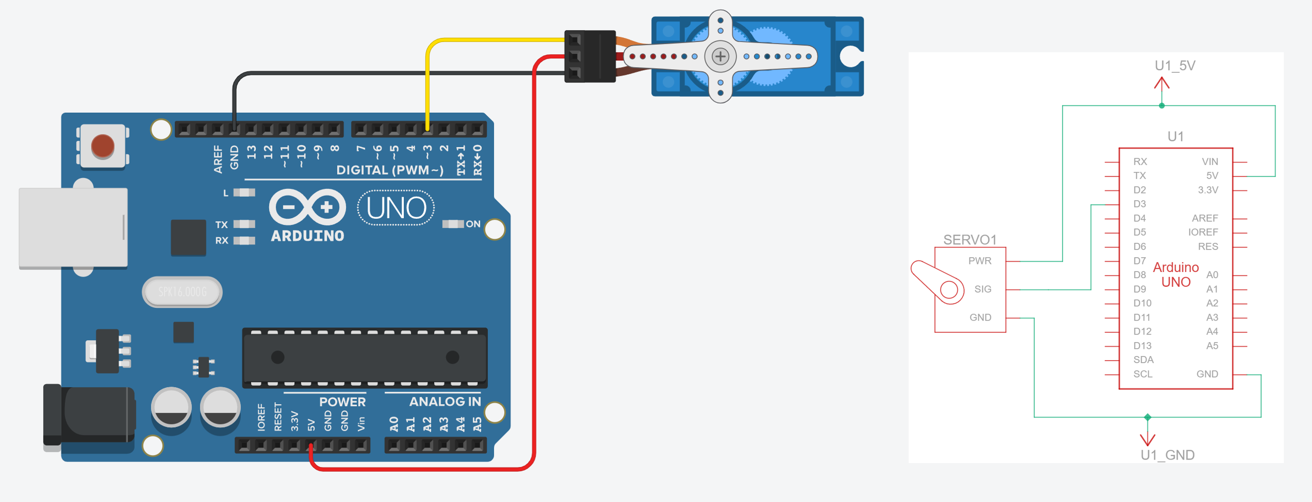 Figure. Wiring the SG90 servo requires just three connections. No transistor or external components needed—the servo has its own built-in driver circuit. Play with this circuit on Tinkercad.
No transistor needed! In the vibromotor lesson, you’ll learn that raw DC motors need a transistor because they draw more current than a GPIO pin can supply. Servos are different—the signal wire carries only a control signal (a few milliamps), not the motor’s power. The servo’s internal driver circuit handles the heavy lifting. The motor power comes directly from the 5V pin, not through the Arduino’s GPIO.
Decoupling capacitor
You may want to add a decoupling capacitor. Servos draw sharp current spikes during rapid movements, which can cause voltage dips that reset the Arduino or introduce jitter. Adding a 100µF electrolytic capacitor across the servo’s power (red) and ground (brown) wires helps absorb these spikes—the same principle as the capacitor recommended for NeoPixels. For multiple servos, use a larger capacitor (470µF or more).
Importantly, electrolytic capacitors are polarized. Be sure to connect the negative leg (marked with a stripe) to ground (GND) and the positive leg to 5V. Reversing them can damage the capacitor.
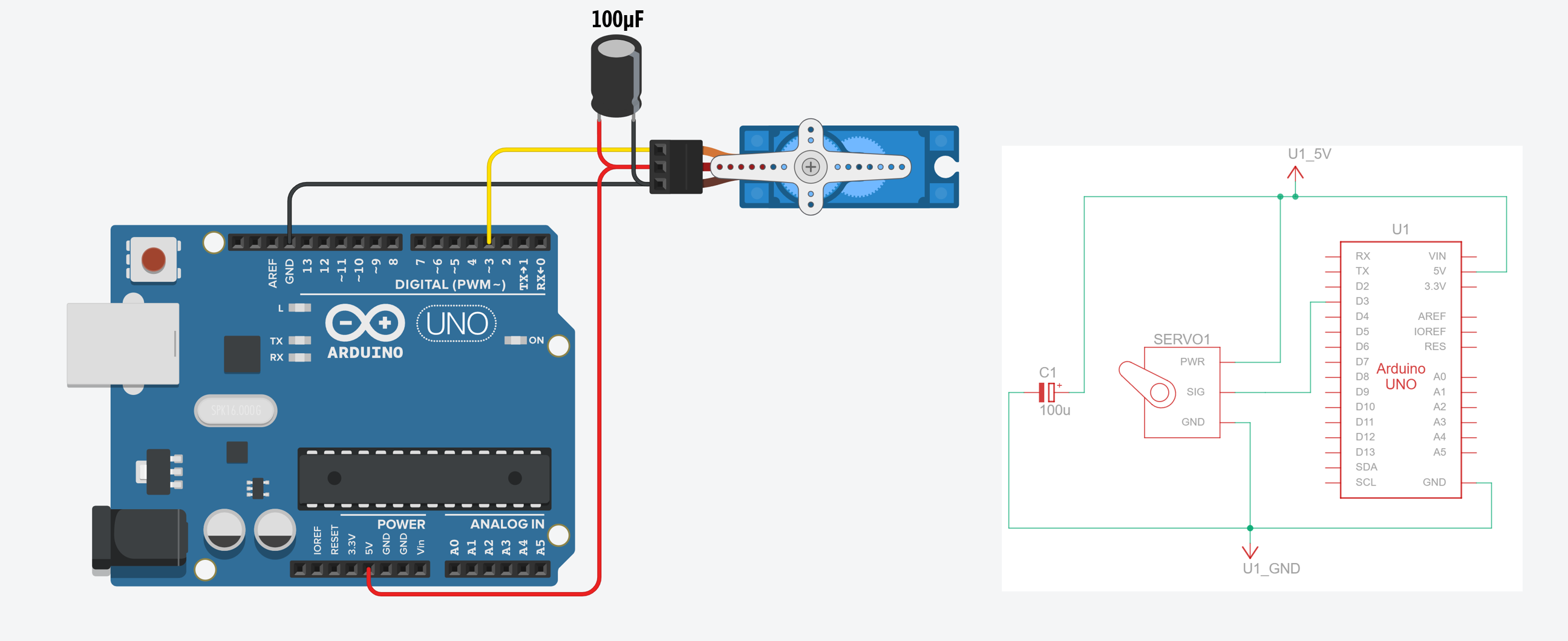 Figure. Wiring the SG90 servo with a 100µF decoupling capacitor across the V+ and GND terminals of the servo. Electrolytic capacitors are polarized: connect the negative leg (marked with a stripe) to GND and the positive leg to 5V. Be sure to connect them properly! Play with this circuit on Tinkercad here.
Power considerations
A single SG90 servo under light load can usually be powered from the Arduino’s 5V pin (via USB). However, servos can draw significant current, especially during rapid movements or when holding position against a load:
| State | Typical current |
|---|---|
| Idle (holding position, no load) | ~6mA |
| Moving (no load) | ~200-500mA |
| Stall (load exceeds torque) | ~500-700mA |
The Arduino’s USB power supply provides about 500mA total. A single SG90 moving under light load is usually fine, but if your servo jitters, stalls, or your Arduino resets, you may be hitting the current limit.
If your Arduino resets when the servo moves, the servo is drawing too much current from USB. Power the servo from an external 5V supply (like a USB phone charger rated 1A+). Connect the supply’s 5V directly to the servo’s red wire and the supply’s GND to both the servo’s brown wire and the Arduino’s GND (shared ground). Do not connect the external 5V to the Arduino’s 5V pin while USB is also connected—this creates conflicting power sources.
For projects with multiple servos, you will almost certainly need an external power supply. Two or more servos moving simultaneously can easily exceed 1A. For larger builds, consider a dedicated servo driver board like the PCA9685, which provides its own power bus and can control up to 16 servos via I2C.
Video. Wiring multiple servo motors together with an external power supply. Importantly, both the Arduino GND and the external power supply GND must be connected. You can play with this multi-servo circuit on Tinkercad here.
Let’s make stuff!
Now that we understand how servos work and have one wired up, let’s build some projects! As with the previous lessons, we’ll start simple and progressively add interactivity.
Activity 1: Servo sweep
Just as we started with blinking an LED and lighting up NeoPixels, let’s start with the simplest possible servo program: sweeping back and forth between 0° and 180°. This confirms your wiring is correct and that the library is communicating with the servo.
#include <Servo.h>

const int SERVO_PIN = 3;
Servo myServo;

void setup() {
  myServo.attach(SERVO_PIN);
}

void loop() {
  // Sweep from 0° to 180°
  for (int angle = 0; angle <= 180; angle++) {
    myServo.write(angle);
    delay(15);  // Wait for the servo to reach the position
  }

  // Sweep back from 180° to 0°
  for (int angle = 180; angle >= 0; angle--) {
    myServo.write(angle);
    delay(15);
  }
}
If you compile this code and it gives an error similar to
Compilation error: Servo.h: No such file or directory, then you need to install the official Arduino servo library authored by Michael Margolis. Open the Library Manager (or go to Sketch > Include Library > Manage Libraries…), search for “Servo”, and scroll to find the Servo library. Then click “Install.”
The delay(15) gives the servo time to reach each position before advancing to the next degree. Try changing the delay—a shorter delay means faster sweeping, but if it’s too short, the servo can’t keep up and will jitter. What happens if you change delay(15) to delay(1)? (Hint: the servo may not have time to reach each position before the next command arrives.) What about changing the range to for (int angle = 30; angle <= 150; ...)?
Avoid driving to the mechanical limits. If your servo makes a grinding or buzzing sound at 0° or 180°, it’s hitting its mechanical stops and stalling. This draws high current and can strip the plastic gears over time. Try reducing your range to 10-170° or experiment to find your servo’s actual safe limits.
Activity 2: Potentiometer-controlled servo
Now let’s add a potentiometer to directly control the servo’s position—turn the knob, and the servo follows. This is the same analogRead() → map() → output pattern from the OLED ball-size demo and the NeoPixel color wheel. You’ll see this pattern again in the vibromotor lesson too—it’s one of the most fundamental patterns in physical computing!
The circuit
Use the same servo wiring as before, and add a 10KΩ potentiometer with its wiper connected to A0.
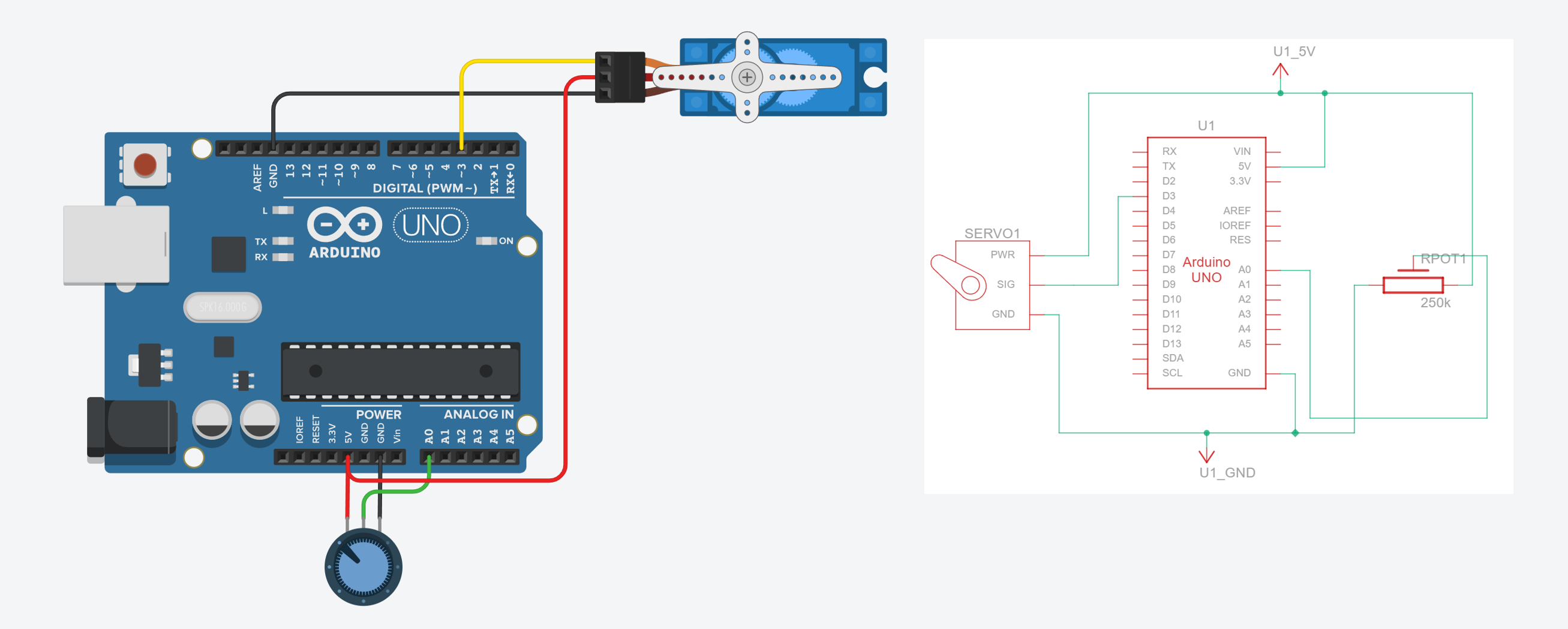 Figure. The wiring diagram for controlling a servo motor with a potentiometer. Play with the circuit on Tinkercad here; alternatively, you can play with this version, which is the same circuit but with the addition of an oscilloscope to see the PWM control waveform.
The code
#include <Servo.h>

const int SERVO_PIN = 3;
const int POT_PIN = A0;

Servo myServo;

void setup() {
  myServo.attach(SERVO_PIN);
  Serial.begin(9600);
}

void loop() {
  // Read the potentiometer (0-1023)
  int potVal = analogRead(POT_PIN);

  // Map to servo angle (0-180)
  int angle = map(potVal, 0, 1023, 0, 180);

  // Move the servo
  myServo.write(angle);

  // Debug output
  Serial.print("Pot: ");
  Serial.print(potVal);
  Serial.print(" -> Angle: ");
  Serial.println(angle);

  delay(15);
}
This is essentially the Arduino’s built-in “Knob” example, which you can also find in the Arduino IDE under File → Examples → Servo → Knob. Turn the potentiometer and watch the servo track your input in real time. Try replacing the potentiometer with a force-sensitive resistor or a photoresistor—squeeze to point, or let light control the angle!
Is your servo jittering? If the servo twitches or vibrates even when you’re not touching the potentiometer, you’re seeing the effect of noisy analog readings. Each time
analogRead()returns a slightly different value, the servo moves to a slightly different angle—fast enough to appear as jitter. A decoupling capacitor can help with power-related jitter, but for signal noise, the real fix is smoothing your input data. In the Smoothing Input lesson, you’ll learn filters like moving average and exponential smoothing that solve exactly this problem. For now, you can also try callingdetach()when the servo doesn’t need to move—this stops the control signal entirely and lets the servo go limp, eliminating jitter at the cost of no longer holding position.
You can hook up an oscilloscope to examine the underlying PWM signal changing with the potentiometer input, which we’ve done in Tinkercad here:
Video. A video of the potentiometer-controlled servo in Tinkercad hooked up to an oscilloscope to show the PWM control signal. Play with the circuit directly here!
The Engineering Mindset YouTube channel did this for real with an oscilloscope, nicely matching the above simulation. Notice how it’s the width of each HIGH pulse that controls the servo’s target angle.
Video. A video snippet from Engineering Mindset showing a potentiometer-controlled PWM waveform driving a servo motor with an Arduino. Notice how the pulse width—the duration of the HIGH pulse within each period—controls the servo’s target angle.
Activity 3: Sensor-driven servo gauge
For our final activity, let’s build a physical gauge—a servo-powered pointer that displays sensor data in the real world, like an analog speedometer or a VU meter needle. This is the physical output equivalent of the OLED analog graph and the NeoPixel level meter. Where the OLED drew data on screen and the NeoPixels lit up LEDs proportionally, here we’ll sweep a physical pointer across a scale.
We’ll read an analog sensor on A0 and map it to the servo’s range. To make it more interesting, we’ll add two buttons: one to “freeze” the gauge at its current reading (like a max-hold feature on a multimeter), and one to reset it.
The circuit
Use the same servo + potentiometer wiring, and add two tactile buttons on Pins 8 and 9 using INPUT_PULLUP.
The code
#include <Servo.h>

const int SERVO_PIN = 3;
const int SENSOR_PIN = A0;
const int FREEZE_BTN = 8;

// The Servo library disables analogWrite() on Pins 9 and 10 on the Uno
// However, you can still use the pins for digitalRead
const int RESET_BTN = 9;

Servo gaugeServo;
bool isFrozen = false;
int frozenAngle = 0;

// State-change detection for buttons
int lastFreezeState = HIGH;
int lastResetState = HIGH;

void setup() {
  gaugeServo.attach(SERVO_PIN);
  pinMode(FREEZE_BTN, INPUT_PULLUP);
  pinMode(RESET_BTN, INPUT_PULLUP);
  Serial.begin(9600);
}

void loop() {
  // Freeze button: toggle on press (state-change detection)
  int freezeState = digitalRead(FREEZE_BTN);
  if (freezeState == LOW && lastFreezeState == HIGH) {
    // Button just pressed (HIGH → LOW transition)
    isFrozen = !isFrozen;
    if (isFrozen) {
      frozenAngle = gaugeServo.read();
      Serial.print("Frozen at: ");
      Serial.println(frozenAngle);
    } else {
      Serial.println("Unfrozen");
    }
    delay(50);  // Brief debounce delay. Careful: this is blocking.
  }
  lastFreezeState = freezeState;

  // Reset button: reset to 0° and freeze there
  int resetState = digitalRead(RESET_BTN);
  if (resetState == LOW && lastResetState == HIGH) {
    isFrozen = true;
    frozenAngle = 0;
    gaugeServo.write(0);
    Serial.println("Reset to 0 (frozen)");
    delay(50);
  }
  lastResetState = resetState;

  // Update gauge if not frozen
  if (!isFrozen) {
    int sensorVal = analogRead(SENSOR_PIN);
    int angle = map(sensorVal, 0, 1023, 0, 180);
    gaugeServo.write(angle);

    Serial.print("Sensor: ");
    Serial.print(sensorVal);
    Serial.print(" -> Angle: ");
    Serial.println(angle);
  }

  delay(15);
}
Notice that the freeze button uses state-change detection rather than simply checking if (digitalRead(FREEZE_BTN) == LOW). The difference is important: without state-change detection, the toggle would fire repeatedly as long as the button is held down (every 15ms through loop()). By tracking lastFreezeState and only acting on the HIGH → LOW transition, we ensure the toggle fires exactly once per button press. The short delay(50) handles contact bounce from the mechanical switch.
servo.read()returns the last written value, not the physical position. When we callgaugeServo.read()to capture the frozen angle, it returns whatever was last passed towrite()—it does not read the potentiometer inside the servo. If you manually move the servo shaft by hand,read()will still return the old value. There is no way to read a standard servo’s actual position from Arduino.
Try attaching a small pointer (a piece of cardboard, a toothpick, or a 3D-printed needle) to the servo horn to create a visual gauge. You could print or draw a scale on paper behind it to complete the analog meter look. This is a great example of physical data visualization—the same sensor data that we graphed on the OLED screen is now embodied as physical motion.
Connecting it all together: At this point, you could combine the servo gauge with an OLED display to show the numeric reading on screen while the servo shows it physically, or with NeoPixels to add color coding (green for low, red for high). Multimodal output—visual, spatial, and haptic—is a powerful tool in physical computing and HCI!
Troubleshooting
If your servo isn’t behaving as expected, work through this list. These are the most common issues students encounter, roughly in order of likelihood:
| Symptom | Likely cause | Fix |
|---|---|---|
| Servo doesn’t move at all | Wrong pin in code | Make sure SERVO_PIN in your sketch matches the physical Arduino pin you wired the signal (orange) wire to. |
| Servo doesn’t move, but gets warm | Signal wire disconnected or not attached in code | Verify the signal wire is connected and that you called myServo.attach(pin) in setup(). |
| Servo jitters or twitches at rest | Noisy analog input or power fluctuations | Add a 100µF capacitor across servo power/GND. If reading a sensor, apply input smoothing. You can also call detach() when the servo doesn’t need to hold position. |
| Servo buzzes or grinds at 0° or 180° | Hitting mechanical stops (stalling) | Reduce your range to 10–170°. Stalling draws high current and can strip plastic gears over time. |
| Arduino resets when servo moves | Current draw exceeds USB power supply capacity | Use an external 5V supply with a shared ground. See Power considerations. |
analogWrite() stopped working on pin 9 or 10 | Servo library claimed Timer1 | The Servo library disables analogWrite() on Timer1 pins even if the servo isn’t on those pins. Use different pins for your PWM outputs. |
| Servo moves erratically or to wrong angles | Using analogWrite() instead of Servo library | Never use analogWrite() to drive a servo. Use myServo.write(angle) instead. |
| Servo overshoots or won’t reach full range | Default pulse width limits don’t match your servo | Use myServo.attach(pin, min, max) with custom microsecond values calibrated to your specific servo. Start with the defaults (544, 2400) and adjust. |
When in doubt, go back to basics. Upload the Activity 1: Servo sweep sketch with no modifications and confirm that the servo sweeps smoothly. If it does, the issue is in your code. If it doesn’t, the issue is in your wiring or power supply.
Exercises
Want to go further? Here are some challenges to reinforce what you’ve learned:
- Servo-powered door lock. Use a button to toggle the servo between “locked” (0°) and “unlocked” (90°) positions. Add an LED that turns green when unlocked and red when locked. You could even attach the servo to a small latch mechanism.
- Light tracker. Mount two photoresistors on either side of a servo. Read both sensors and turn the servo toward whichever side detects more light—a simple solar tracker!
- Servo + OLED dashboard. Display the current servo angle, sensor reading, and servo state (frozen/unfrozen) on the OLED display while the gauge moves. This combines two lessons into a multimodal output project.
- Animatronic face. If you have two servos, mount them to control the horizontal and vertical movement of a pair of eyes (drawn or 3D-printed). Use two potentiometers—or an accelerometer—as input for a fun animatronic project.
- Servo + NeoPixel indicator. Sweep a servo based on a sensor reading while simultaneously changing the NeoPixel strip’s color to match the angle—blue at 0°, green at 90°, red at 180°. This is a good exercise in managing Timer1 pin conflicts (remember, the Servo library disables
analogWrite()on certain pins, but the NeoPixel library uses its own timing on any digital pin).
Lesson Summary
In this lesson, you learned how to control servo motors for precise angular positioning. The key concepts were:
- Servo motors contain a DC motor, gears, a position-sensing potentiometer, and a control circuit in one package. This closed-loop feedback system lets you command a specific angle and the servo figures out how to get there.
- Standard servos rotate to a specific angle (typically 0-180°) and hold position. Continuous rotation servos control speed and direction instead.
- Servo PWM is different from
analogWrite()PWM in purpose, not just frequency. Both have a duty cycle, butanalogWrite()PWM modulates power (the load sees average voltage), while servo PWM encodes a position command (the control circuit measures the pulse width). Servos expect a 50 Hz signal where the pulse width (~1–2ms) encodes the target angle.analogWrite()produces 490–980 Hz PWM for power control. Never useanalogWrite()to drive a servo. - The Arduino Servo library generates the correct 50 Hz signal for you. Like the NeoPixel library, it works on any digital pin—no hardware PWM required.
- Unlike raw DC motors (covered in the next lesson), no transistor is needed because the signal wire carries only a low-current control signal. The servo’s internal circuit handles motor power.
- The Servo library uses Timer1, which disables
analogWrite()on Pins 9 and 10 (Uno) or Pins 9, 10, and 11 (Leonardo). Plan your pin assignments accordingly when combining servos with other PWM outputs. - For multiple servos or heavy loads, use an external 5V power supply with a shared ground connection to the Arduino—the same principle we’ll encounter again in the vibromotor lesson.
- A 100µF decoupling capacitor across the servo’s power and ground wires helps absorb current spikes during rapid movements, reducing jitter and preventing Arduino resets.
- Calling
detach()stops the control signal, letting the servo go limp. This saves power and eliminates jitter when you don’t need the servo to actively hold position—useful for battery-powered projects.
Resources
-
Arduino Servo Library Reference, Arduino.cc
-
Servo Motor Basics with Arduino, Arduino Docs
-
Adafruit Motor Selection Guide, Adafruit — helps you choose the right motor type for your project
-
PCA9685 16-Channel Servo Driver, Adafruit — for projects needing many servos
Next Lesson
In the next lesson, we will shift from components with built-in intelligence to a raw DC motor—the vibromotor. You’ll learn why transistors, flyback diodes, and resistor calculations become necessary when a component doesn’t have its own driver circuit.