Lesson 4: Analog input
Table of Contents
- Materials
- Analog input on the ESP32
- Let’s build a potentiometer-controlled LED fader!
- Bonus: Potentiometer-controlled NeoPixel hue 🌈
- Summary
- Exercises
- Next Lesson
In the last lesson, we used the LEDC library to control an LED’s brightness with PWM—but the brightness was hardcoded in a for loop. Wouldn’t it be more fun to control the brightness with a physical knob? In this lesson, we’ll combine analog input (reading a potentiometer) with analog output (PWM) to build a hands-on LED fader. Along the way, you’ll learn how the ESP32’s ADC differs from the Arduino Uno’s and why it matters.
This lesson mirrors the potentiometers lesson in the “Intro to Arduino” series. If you’ve forgotten how potentiometers work, we recommend consulting that lesson first as a refresh.
Video. Using a potentiometer to control the LED brightness on the Adafruit ESP32-S3.
In this lesson, you will learn:
- How to read analog input on the ESP32 using
analogRead()- Why the ESP32 has a 12-bit ADC (0–4095) instead of the Arduino Uno’s 10-bit ADC (0–1023)
- How to use
map()to convert between different value ranges- How to combine analog input with PWM output to build a physical LED dimmer
- Which analog pins to use on the ESP32-S3 Feather (and why ADC1 pins are special)
- How to write portable code that works on both ESP32 and Arduino using preprocessor defines
- How to control the onboard NeoPixel’s color with a potentiometer
Materials
You’ll need the same materials as the last lesson plus a potentiometer. We use Adafruit’s ESP32-S3 Feather but any ESP32-S3 board will work!
| Breadboard | ESP32 | LED | Resistor | Trimpot |
|---|---|---|---|---|
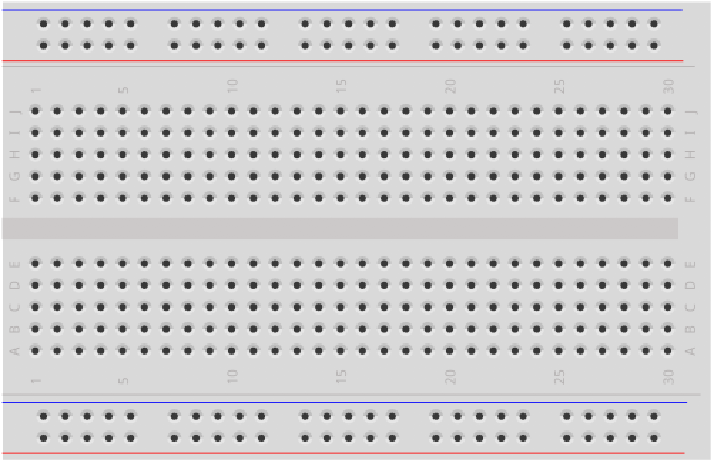 | 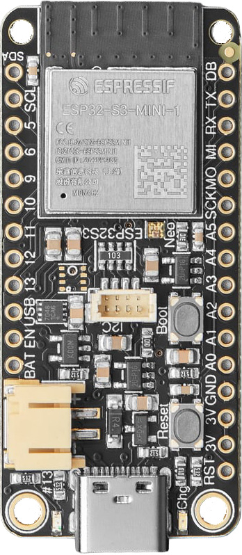 | 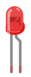 | 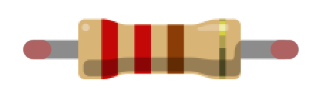 |  |
| Breadboard | ESP32-S3 Feather | Red LED | 220Ω Resistor | 10kΩ Trimpot |
If you haven’t used a potentiometer before, see our Potentiometers lesson in the Intro to Arduino series. It covers how potentiometers work as voltage dividers, how to wire them, and how
analogRead()converts a voltage into a number.
Analog input on the ESP32
If you completed the Arduino Potentiometers lesson, you already know how analogRead() works: the ADC (analog-to-digital converter) samples the voltage on a pin and returns a digital number proportional to that voltage. The good news is that analogRead() works exactly the same on the ESP32—no new functions to learn!
The key differences are in the hardware.
12-bit ADC (0–4095)
The Arduino Uno has a 10-bit ADC, so analogRead() returns values from 0 to \(2^{10}-1 = 1023\). The ESP32 has a 12-bit ADC, so analogRead() returns values from 0 to \(2^{12}-1 = 4095\). This means the ESP32 can distinguish finer voltage differences—each step represents about 0.8mV (that is, \(3.3\text{V} \div 4096 \approx 0.0008\text{V}\)) compared to the Uno’s ~4.9mV per step (\(5\text{V} \div 1024 \approx 0.0049\text{V}\)).
Don’t forget: The ESP32 operates at 3.3V, not 5V. So
analogRead()returns 4095 at 3.3V, not at 5V. If you’re porting Arduino Uno code that assumes a 0–1023 range or a 5V reference, you’ll need to update those values!
ADC pins: chip vs. board
The ESP32-S3 chip integrates two 12-bit SAR (Successive Approximation Register) ADCs supporting 20 channels total: ADC1 has 10 channels (GPIO1–GPIO10) and ADC2 has 10 channels (GPIO11–GPIO20). However, not all 20 are broken out on every development board—the board manufacturer chooses which GPIOs to expose on the header pins.
On the Adafruit ESP32-S3 Feather, 15 ADC-capable pins are available. Six carry the conventional Arduino “A” prefix (A0–A5), but this labeling is just an Arduino ecosystem convention for discoverability—it doesn’t indicate special hardware. Electrically, analogRead(A5) and analogRead(9) use the exact same 12-bit SAR ADC, and any ADC-capable GPIO works identically with analogRead():
| Pin label | GPIO | ADC | Channel |
|---|---|---|---|
| A0 | GPIO18 | ADC2 | CH7 |
| A1 | GPIO17 | ADC2 | CH6 |
| A2 | GPIO16 | ADC2 | CH5 |
| A3 | GPIO15 | ADC2 | CH4 |
| A4 | GPIO14 | ADC2 | CH3 |
| A5 | GPIO8 | ADC1 | CH7 |
| D5 | GPIO5 | ADC1 | CH4 |
| D6 | GPIO6 | ADC1 | CH5 |
| D9 | GPIO9 | ADC1 | CH8 |
| D10 | GPIO10 | ADC1 | CH9 |
| D11 | GPIO11 | ADC2 | CH0 |
| D12 | GPIO12 | ADC2 | CH1 |
| D13 | GPIO13 | ADC2 | CH2 |
| SDA | GPIO3 | ADC1 | CH2 |
| SCL | GPIO4 | ADC1 | CH3 |
Pin names in code: The
A0–A5labels are defined as macros in the ESP32 Arduino core (e.g.,A5maps to GPIO8), soanalogRead(A5)works as expected. However, the “D” prefix on the silkscreen (e.g., D5, D9) is not defined in code—analogRead(D5)won’t compile. For those pins, use the GPIO number directly:analogRead(5)for the pin labeled D5,analogRead(9)for D9, and so on.
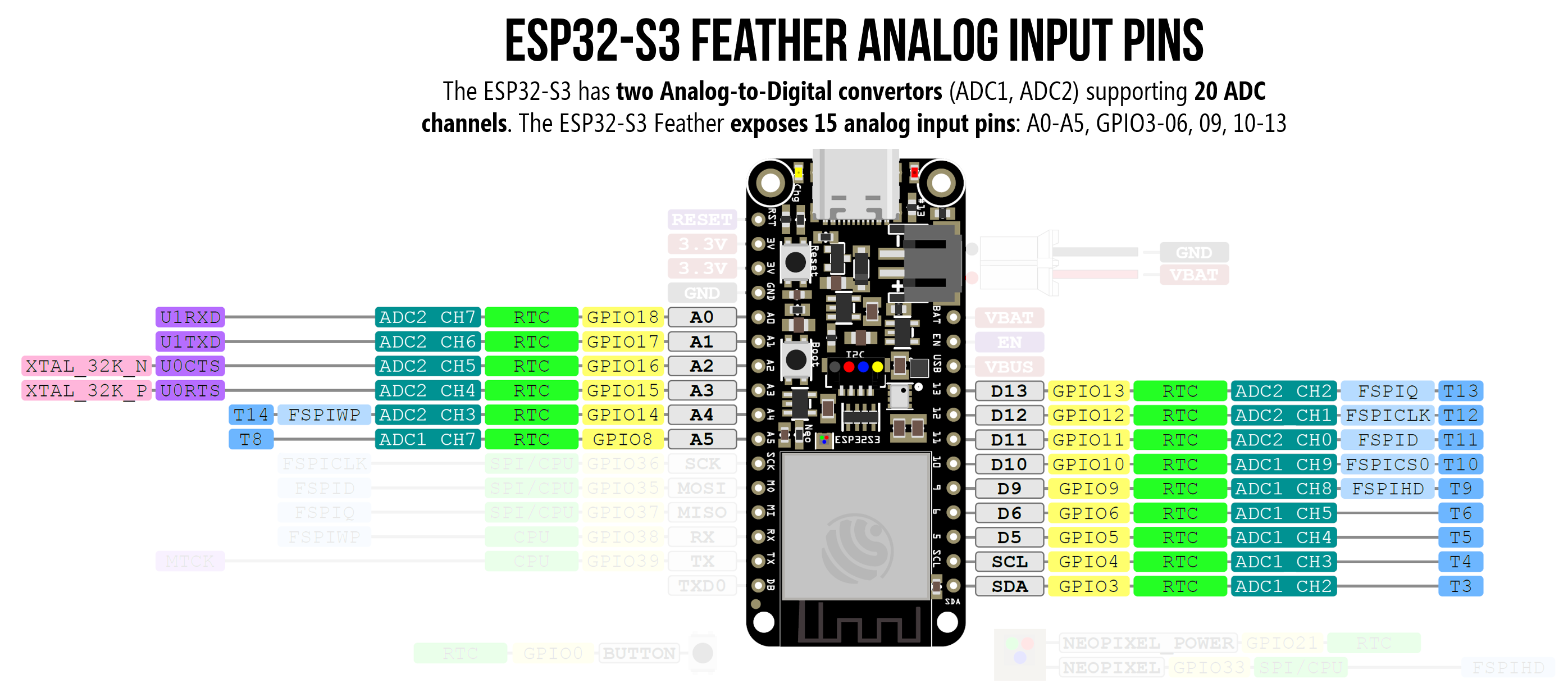 Figure. Pin diagram for the Adafruit ESP32-S3 Feather highlighting the 15 ADC-capable pins. The “A0–A5” labels are an Arduino convention; the nine other ADC pins (D5, D6, D9–D13, SDA, SCL) are functionally identical for analog input. Note that ADC1 pins (A5, D5, D6, D9, D10, SDA, SCL) work even when WiFi is active, while ADC2 pins (A0–A4, D11–D13) do not. See the Adafruit pinouts guide for details.
ADC2 and WiFi
Why does the ADC1 vs. ADC2 distinction matter? Because ADC2 is shared with the WiFi radio—a hardware limitation on all ESP32 variants. On the original ESP32, ADC2 reads fail outright when WiFi is active (returning ESP_ERR_TIMEOUT). The ESP32-S3 improves on this with a hardware arbiter that allows ADC2 and WiFi to share access, but WiFi has higher priority—so ADC2 reads will intermittently return invalid data under WiFi traffic. The practical advice is the same: if your project uses WiFi and analog input simultaneously, use an ADC1 pin.
For this lesson, we’ll use A5 for our potentiometer input. A5 is on ADC1, which means it works whether WiFi is on or off—a good habit to build for when you add WiFi in Lesson 7. If you need more WiFi-compatible analog inputs, D5, D6, D9, and D10 are also on ADC1 (though SDA and SCL are typically reserved for I2C).
ADC nonlinearity
The ESP32’s ADC is known to be somewhat nonlinear at the extremes of its range—readings below ~100mV and above ~3.2V can be inaccurate. You may notice that your potentiometer doesn’t quite reach 0 or 4095 at the endpoints. In practice, this can feel like a small “dead zone” at the physical extremes of the knob—the LED stops changing brightness slightly before the knob reaches its endpoint. The ESP32-S3 is significantly better than the original ESP32 in this regard, thanks to a built-in hardware calibration circuit. For most interactive projects (like our LED fader), this nonlinearity is negligible. For precision measurement, Espressif provides ADC calibration APIs in the ESP-IDF.
Changing the ADC resolution
If you’re porting Arduino Uno code and don’t want to change all your 0–1023 constants, you can tell the ESP32 to use 10-bit resolution instead:
analogReadResolution(10); // Now analogRead() returns 0-1023, like the Uno
We won’t use this in our lesson (we’ll embrace the full 12-bit range), but it can be useful when migrating existing code.
Writing portable code with preprocessor defines
A more flexible approach to portability is to use preprocessor defines—conditional blocks that the C/C++ preprocessor evaluates before compilation. The Arduino build system automatically defines certain symbols for each board: ESP32 is defined when compiling for any ESP32 board, while symbols like ARDUINO_AVR_UNO or ARDUINO_AVR_LEONARDO identify those boards.
Here’s a pattern you’ll see in many of our examples:
// The preprocessor evaluates these BEFORE compilation.
// Only the matching block is included in the final program.
#if defined(ESP32)
  const int MAX_ANALOG_VAL = 4095;   // ESP32 has a 12-bit ADC (0-4095)
#else
  const int MAX_ANALOG_VAL = 1023;   // AVR Arduinos have a 10-bit ADC (0-1023)
#endif
When you compile for the ESP32-S3, the preprocessor sees that ESP32 is defined and includes 4095. When you compile for the Arduino Uno, ESP32 is not defined, so it falls through to the #else block and uses 1023. The rest of your code just uses MAX_ANALOG_VAL and works on both boards without any changes.
You’ve already seen this mechanism in action! The
#if defined(NEOPIXEL_POWER)guard we used in blinking on the on-board NeoPixel in the LED blink lesson works the same way. The board support package definesNEOPIXEL_POWERonly for boards that have a NeoPixel power pin. If the symbol isn’t defined, the code inside the block is silently skipped.
We’ll use this pattern in our pot-fade code below.
Using the Huzzah32 instead? (click to expand)
Huzzah32 ADC pin diagram
The Huzzah32 uses the original ESP32, which has a different set of ADC pins:
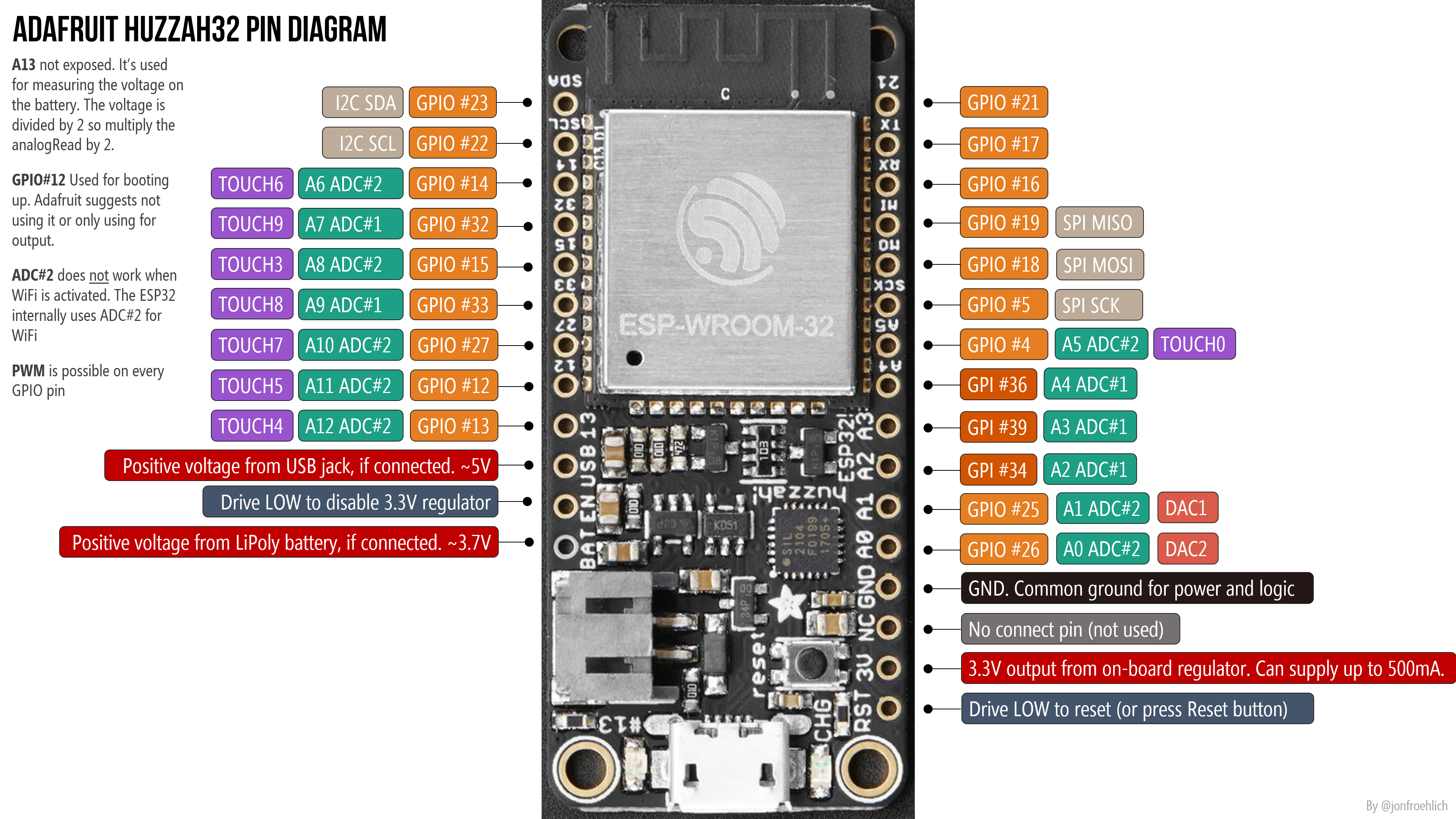 Figure. Huzzah32 pin diagram. ADC pins are marked in teal. Right-click and open in a new tab to zoom in.
The pin assignments on the Huzzah32:
- ADC1 has 8 channels on GPIOs 32–39, which map to A7 (32), A9 (33), A2 (34), A4 (36), and A3 (39). GPIOs 35, 37, and 38 are not exposed on the Huzzah32.
- ADC2 has 10 channels on GPIOs 0, 2, 4, 12–15, and 25–27, which map to A5 (4), A11 (12), A12 (13), A6 (14), A8 (15), A1 (25), A0 (26), A10 (27). GPIOs 0 and 2 are not exposed.
In total, the Huzzah32 has 13 usable analog inputs (A0–A12). Our original code examples use A6 (GPIO 14) for the potentiometer input.
ADC2 and WiFi on the Huzzah32
The same ADC2/WiFi restriction applies: ADC2 pins are unavailable when WiFi is active. On the Huzzah32, ADC1 has more pins (GPIOs 32–39), so you have more options for WiFi-compatible analog input.
The official Adafruit Huzzah32 docs contain a confusing statement: “you can only read analog inputs on ADC #1 once WiFi has started.” This is misleading—they mean that only ADC1 works when WiFi is active (ADC2 does not). We confirmed this through experimentation.
Huzzah32 workbench videos
In the following video, we test all 13 analog input pins (A0–A12) using a trim potentiometer for input and the Serial Plotter for output:
Video. Testing all 13 analog input pins on the Adafruit ESP32 Huzzah32 with a potentiometer and the Serial Plotter.
Let’s build a potentiometer-controlled LED fader!
Now let’s put analog input and PWM output together. We’ll read the potentiometer’s position with analogRead() and use that value to control the LED’s brightness with ledcWrite(). This is exactly what we did in the potentiometers lesson in the “Intro to Arduino” series.
The circuit
We’re combining two simple circuits:
- Input: A 10kΩ potentiometer connected to A5 (the ADC1 pin). Wire the outer legs to 3.3V and GND, and the center wiper to A5.
- Output: An LED on GPIO 13 through a 220Ω resistor (same as the Blink and Fade lessons)
Here’s the circuit diagram showing a no breadboard version (perhaps wired with alligator clips), a breadboarded version, and a schematic.
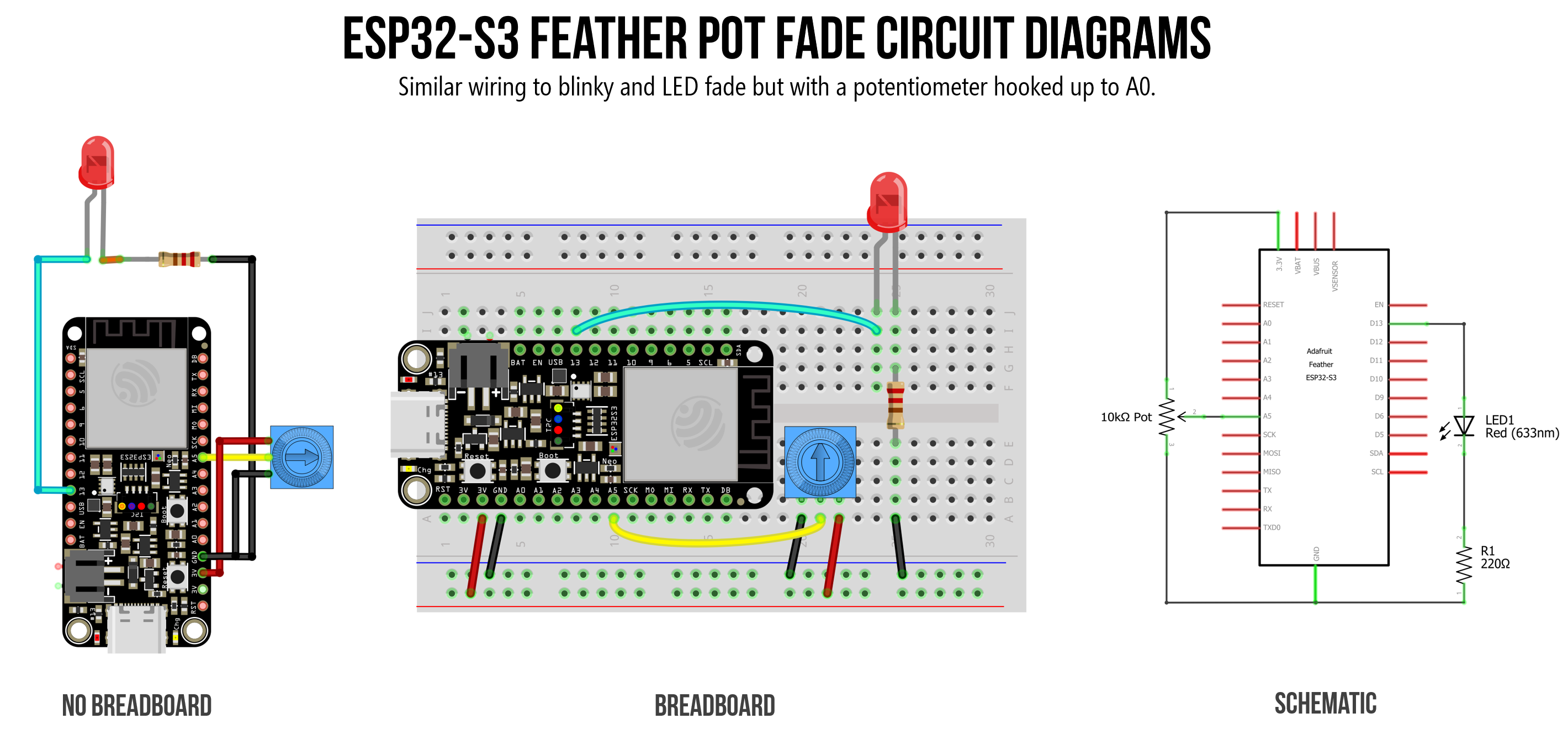 Figure. Circuit diagram showing a potentiometer on A5 (analog input) and an LED on GPIO 13 (PWM output) on the ESP32-S3 Feather.
Using the Huzzah32 instead? (click to expand)
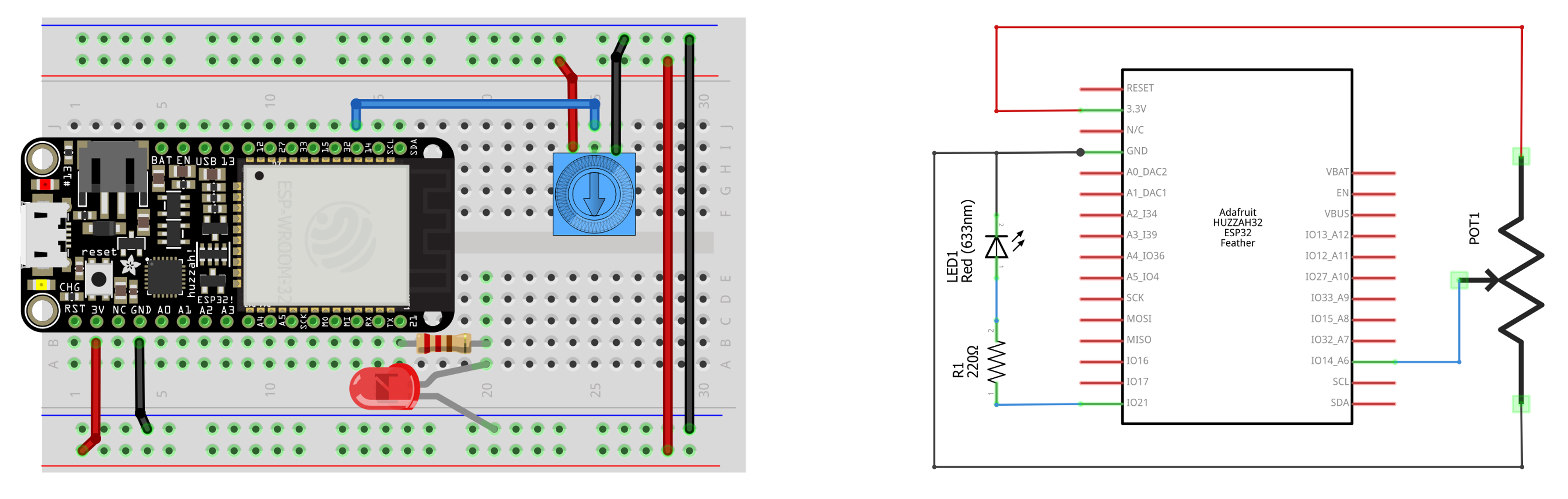 Figure. Huzzah32 circuit with potentiometer on A6 (GPIO 14) and LED on GPIO 21.
The code
The core idea is simple: read the potentiometer → convert the value → write to the LED. But because the ADC and PWM use different ranges, we need the map() function to translate between them.
/**
 * Reads a potentiometer on A5 and uses the value to control
 * LED brightness via PWM on GPIO 13.
 *
 * Demonstrates: analogRead (12-bit), map(), ledcWrite (8-bit PWM),
 * and preprocessor defines for portable code.
 *
 * See: https://makeabilitylab.github.io/physcomp/esp32/pot-fade
 */

// Preprocessor defines for cross-platform portability ---
#if defined(ESP32)
  const int MAX_ANALOG_VAL = 4095;  // ESP32 has a 12-bit ADC (0-4095)
#else
  const int MAX_ANALOG_VAL = 1023;  // AVR Arduinos have a 10-bit ADC (0-1023)
#endif

const int LED_OUTPUT_PIN = 13; // GPIO 13 = LED_BUILTIN on ESP32-S3 Feather
const int POT_INPUT_PIN = A5;  // A5 is on ADC1; works even when WiFi is active

const int PWM_FREQ = 5000;     // 5 kHz PWM frequency
const int PWM_RESOLUTION = 8;  // 8-bit resolution: duty cycle 0-255
const int MAX_DUTY_CYCLE = (1 << PWM_RESOLUTION) - 1;  // 2^8 - 1 = 255

void setup() {
  Serial.begin(115200);

  // Attach PWM to the LED pin (v3.x API — channel assigned automatically)
  ledcAttach(LED_OUTPUT_PIN, PWM_FREQ, PWM_RESOLUTION);
}

void loop() {
  // Read the potentiometer (returns 0-4095 on the ESP32's 12-bit ADC)
  int potVal = analogRead(POT_INPUT_PIN);

  // Map the 12-bit input (0-4095) to the 8-bit PWM range (0-255)
  int dutyCycle = map(potVal, 0, MAX_ANALOG_VAL, 0, MAX_DUTY_CYCLE);

  // Set the LED brightness
  ledcWrite(LED_OUTPUT_PIN, dutyCycle);

  // Print both values for debugging (use Serial Plotter to visualize!)
  Serial.print("PotVal:");
  Serial.print(potVal);
  Serial.print(", DutyCycle:");
  Serial.println(dutyCycle);

  delay(10);  // Small delay for stable readings
}
Let’s walk through the key parts.
Preprocessor defines
At the top, we use #if defined(ESP32) to set MAX_ANALOG_VAL to the correct value for whichever board we’re compiling for. This means the same code works on both an ESP32 and an Arduino Uno without modification—the preprocessor handles the difference before the compiler ever sees it.
The map() function
The potentiometer gives us a value from 0 to 4095 (12-bit ADC), but ledcWrite expects 0 to 255 (8-bit PWM). The map() function performs this linear conversion for us:
// The map function takes (value, fromLow, fromHigh, toLow, toHigh)
int dutyCycle = map(potVal, 0, MAX_ANALOG_VAL, 0, MAX_DUTY_CYCLE);
So map(2048, 0, 4095, 0, 255) returns ~127 (approximately half brightness). You could also do this with integer math (potVal * 255 / 4095), but map() is more readable and generalizes to any range conversion.
The
map()function uses integer math only—no floating point. This means the output can be off by 1 due to rounding, which is perfectly fine for LED brightness. If you ever need precise floating-point mapping, you’ll need to write your own function.
Why A5?
We chose A5 because it’s on ADC1 on the ESP32-S3 Feather. While A0–A4 would also work for this lesson (since we’re not using WiFi), using A5 is a good habit. When you add WiFi in Lesson 7, your analog input will keep working without any rewiring. If you need additional WiFi-compatible analog pins, D5, D6, D9, and D10 are also on ADC1.
Serial Plotter tip: The
Serial.printformat used above ("PotVal:"followed by the value, then a comma separator) is designed for the Arduino IDE’s Serial Plotter. Open it with Tools → Serial Plotter to see a real-time graph of both the potentiometer input and the duty cycle output. It’s a great way to visualize what your code is doing!
Workbench video of pot-controlled LED with ledcWrite()
Video. Using a potentiometer to control the LED brightness on the Adafruit ESP32-S3 with ledcWrite().
Huzzah32 workbench video (click to expand)
Here’s a workbench video showing the pot-fade circuit on the Huzzah32, with the Serial Plotter graphing the analog input value and the converted duty cycle:
Video. Potentiometer-controlled LED fader on the Huzzah32 with Serial Plotter output.
Try pot-fade in Wokwi
Video. The potentiometer-controlled LED brightness circuit and sketch running in the Wokwi simulator on the ESP32-S3 DevKitC. Run it yourself on Wokwi here.
You can also build this circuit yourself in the Wokwi simulator. Add a potentiometer and an LED to the ESP32-S3 DevKitC, and use the same code above. Or, you can start with our version and modify it.
→ Open the Pot Fade simulation in Wokwi
Using analogWrite instead
Just like in the LED fade lesson, you can simplify the output side by using analogWrite() instead of the LEDC API, which defaults to 1kHz PWM waveforms at 8-bit resolution.
/**
 * Potentiometer-controlled LED fader using analogWrite().
 * Same behavior as the LEDC version, but simpler code.
 *
 * See: https://makeabilitylab.github.io/physcomp/esp32/pot-fade
 */

#if defined(ESP32)
  const int MAX_ANALOG_VAL = 4095;
#else
  const int MAX_ANALOG_VAL = 1023;
#endif

const int LED_OUTPUT_PIN = 13;
const int POT_INPUT_PIN = A5;

void setup() {
  // Set the LED output pin
  pinMode(LED_OUTPUT_PIN, OUTPUT);
}

void loop() {
  int potVal = analogRead(POT_INPUT_PIN);

  // analogWrite expects 0-255; analogRead returns 0-4095 on ESP32
  int brightness = map(potVal, 0, MAX_ANALOG_VAL, 0, 255);
  analogWrite(LED_OUTPUT_PIN, brightness);

  delay(10);
}
This is even simpler—no ledcAttach, no frequency or resolution constants. The tradeoff is the same as in the fade lesson: you’re stuck with analogWrite’s default 1 kHz / 8-bit PWM unless you explicitly override it.
Workbench video of pot-controlled LED with analogWrite()
Video. Using a potentiometer to control the LED brightness on the Adafruit ESP32-S3 with analogWrite(). The behavior is indistinguishable from the ledcWrite() version.
Bonus: Potentiometer-controlled NeoPixel hue 🌈
In the last lesson’s bonus section, we faded the NeoPixel through the color wheel automatically. Now let’s put you in control—map the potentiometer to the hue so you can dial in any color you want!
/**
 * Maps potentiometer input to the onboard NeoPixel's hue.
 * Turn the knob to sweep through the full rainbow!
 *
 * Requires the Adafruit NeoPixel library:
 *   Sketch -> Include Library -> Manage Libraries -> search "Adafruit NeoPixel"
 *
 * See: https://makeabilitylab.github.io/physcomp/esp32/pot-fade
 */
#include <Adafruit_NeoPixel.h>

Adafruit_NeoPixel _pixel(1, PIN_NEOPIXEL, NEO_GRB + NEO_KHZ800);

const int POT_INPUT_PIN = A5;            // ADC1 pin — works with WiFi too

#if defined(ESP32)
  const int MAX_ANALOG_VAL = 4095;
#else
  const int MAX_ANALOG_VAL = 1023;
#endif

const uint32_t MAX_HUE = 65536;          // Full color wheel in 16-bit hue

void setup() {
  #if defined(NEOPIXEL_POWER)
    pinMode(NEOPIXEL_POWER, OUTPUT);
    digitalWrite(NEOPIXEL_POWER, HIGH);
  #endif

  _pixel.begin();
  _pixel.setBrightness(30);  // Keep it gentle on the eyes
  _pixel.show();

  Serial.begin(115200);
}

void loop() {
  // Read the potentiometer (0-4095 on ESP32)
  int potVal = analogRead(POT_INPUT_PIN);

  // Map to the full hue range (0-65535)
  uint32_t hue = map(potVal, 0, MAX_ANALOG_VAL, 0, MAX_HUE - 1);

  // Apply the hue with full saturation and brightness, plus gamma correction
  uint32_t color = _pixel.gamma32(_pixel.ColorHSV(hue, 255, 255));
  _pixel.setPixelColor(0, color);
  _pixel.show();

  Serial.print("Pot:");
  Serial.print(potVal);
  Serial.print(", Hue:");
  Serial.println(hue);

  delay(20);
}
Turn the potentiometer slowly and watch the NeoPixel sweep through the entire rainbow—from red through orange, yellow, green, cyan, blue, purple, and back to red. This is the same analogRead() → map() → output pattern, just with a different (and more colorful!) output device.
Challenge: Can you add a second potentiometer to control brightness independently? Map the second pot (on a different analog pin) to the third argument of
ColorHSV()(the value/brightness parameter, 0–255). Now you have two-axis control: one knob for color, one for brightness!
Using the Huzzah32 instead? (click to expand)
The original Huzzah32 does not have an onboard NeoPixel. You can connect an external NeoPixel to a GPIO pin and update PIN_NEOPIXEL accordingly. See the Addressable LEDs lesson for wiring details.
Workbench video of pot-controlled LED with analogWrite()
Video. Using a potentiometer to control the hue of the built-in NeoPixel on the Adafruit ESP32-S3.
Try Pot-controlled RGB crossfade in Wokwi
Video. The potentiometer-controlled RGB cross-fade circuit and sketch running in the Wokwi simulator on the ESP32-S3 DevKitC. Run it yourself on Wokwi here.
You can also build this circuit yourself in the Wokwi simulator or you can start with our version and modify it.
→ Open the Pot RGB cross fade simulation in Wokwi
Summary
In this lesson, you combined analog input with PWM output to build a physical LED dimmer—and controlled the NeoPixel’s color with a knob! The key takeaways:
analogRead()works the same on the ESP32 as on the Arduino Uno—but the ESP32’s 12-bit ADC returns values from 0 to 4095 (compared to the Uno’s 10-bit range of 0–1023). Don’t forget to update your constants when porting code!- The ESP32-S3 chip has 20 ADC channels total (10 on ADC1, 10 on ADC2). The Adafruit ESP32-S3 Feather exposes 15 of these. The “A0–A5” labels are an Arduino convention—pins like D5, D6, D9, and D10 are equally capable analog inputs using the same ADC hardware. Only A5 among the “A”-labeled pins is on ADC1. In code, use
analogRead(A5)for “A”-prefixed pins, butanalogRead(5)(the GPIO number) for “D”-prefixed pins like D5. - ADC2 is unavailable when WiFi is active—a hardware limitation on all ESP32 variants. Use ADC1 pins if your project needs both WiFi and analog input.
- The
map()function is essential for converting between different value ranges—in this case, mapping 12-bit ADC input (0–4095) to 8-bit PWM output (0–255). - Preprocessor defines (
#if defined(ESP32)) let you write a single codebase that compiles correctly on both ESP32 and Arduino boards—the preprocessor swaps in the right constants before compilation. - The
analogRead()→map()→ output pattern is one of the most common patterns in physical computing. Once you can read a sensor and map its value to an output, you can build almost anything!
Exercises
Exercise 1: Modify the pot-fade code to print the potentiometer reading as a voltage instead of a raw ADC value. The formula is: \(V = \frac{analogRead \times 3.3}{4095}\). Make sure to store the result in a float (not an int), or you’ll only see whole numbers! Compare your Serial Monitor output to a multimeter reading on the potentiometer’s wiper pin.
Exercise 2: Instead of controlling brightness, use the potentiometer to control the blink rate of the LED. Map the pot value to a delay between 50ms (fast blinking) and 1000ms (slow blinking). Use digitalWrite for the blinking—no PWM needed.
Exercise 3: Add a second potentiometer to the NeoPixel bonus circuit. Use one pot for hue (A5) and one for brightness (on another analog pin). Map the second pot to the value parameter of ColorHSV() (0–255). Now you have two-knob color control!
Exercise 4: Slowly turn the potentiometer from one end to the other while watching the Serial Plotter. Is the ramp perfectly linear, or do you see any irregularity at the extremes (near 0 or 4095)? This is the ESP32 ADC nonlinearity in action—though the ESP32-S3’s hardware calibration makes it much better than the original ESP32.
Exercise 5: Try adding analogReadResolution(10) to setup(). What range does analogRead() return now? Update your map() call accordingly. Why might this be useful when porting code from an Arduino Uno?
Next Lesson
In the next lesson, we’ll learn how to play tones and melodies on the ESP32 using the LEDC PWM library—the same hardware we used for LED fading, but now driving a speaker instead of an LED!